
ElectricalPower cable size selectionIn most EVs I've been involved with building, we've used 50mm² power cable for the traction circuit. Sometimes I'd use 95mm² between controller and motor, where average currents are higher. Compared with 95mm², 50mm² cable is much easier to work with - lighter, smaller, cheaper, and half the bend radius. But of course 95mm² can handle more current. (Though the relationship is not linear, because smaller cables have greater surface area per mm² copper, so radiate heat more effectively.) I did a few calculations to see if it would be worth running 95sqmm for the whole car - especially considering losses between front and rear battery pack.
Heat generation at the continuous current rating is very minimal (seems to me like official current ratings are very conservative), but since power increases with the square of current, losses become significant during the intermittent peaks. Although resistances of 1-2mΩ don't sound like much, when the peak battery current could be as high as 1000A, the P=I²R becomes quite significant, and I worry about the 50mm² cable getting too hot. So I decided to go with 95mm² throughout.
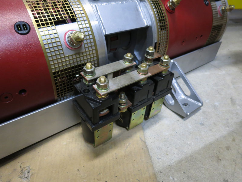
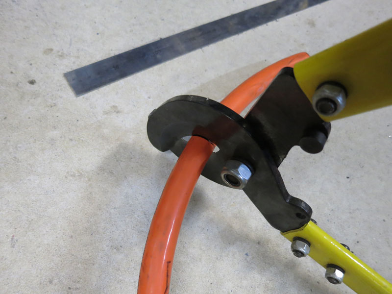
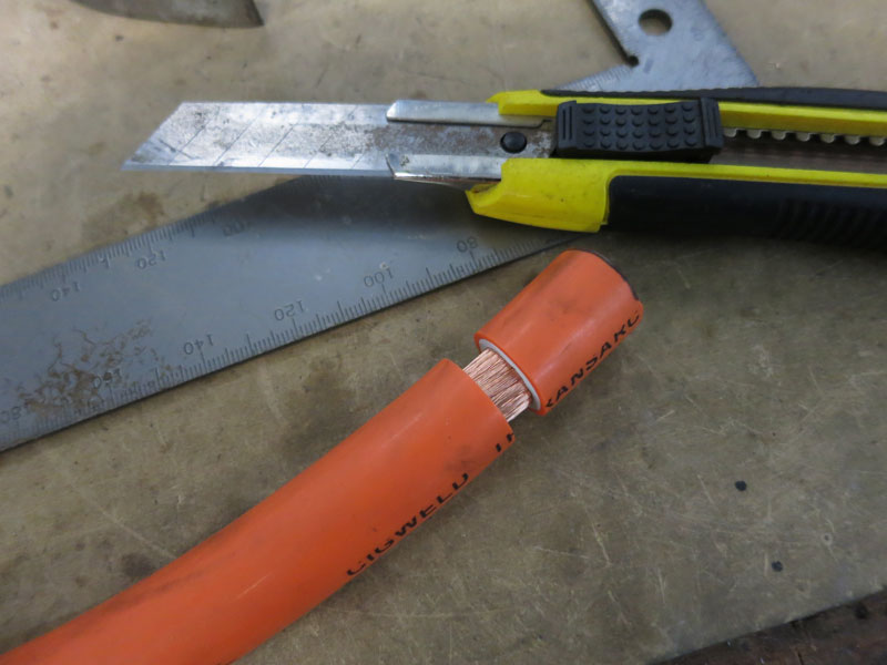
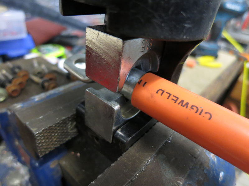
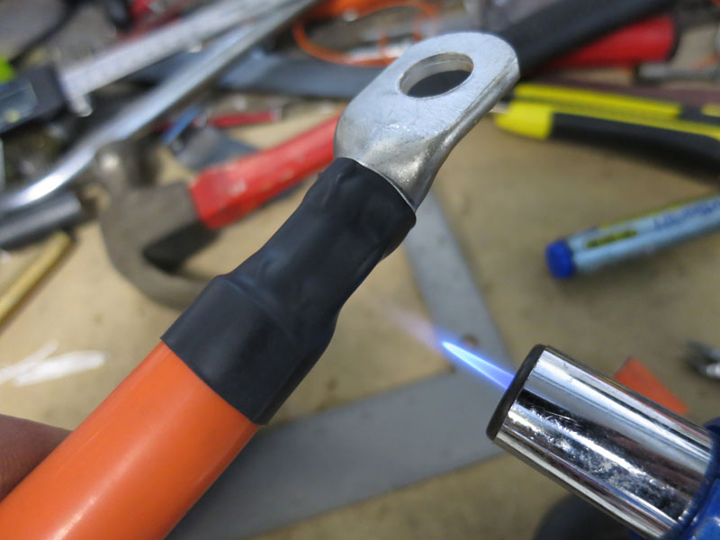
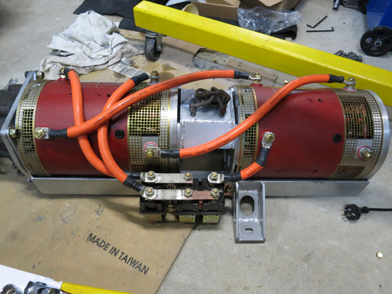
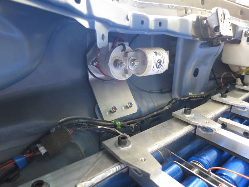
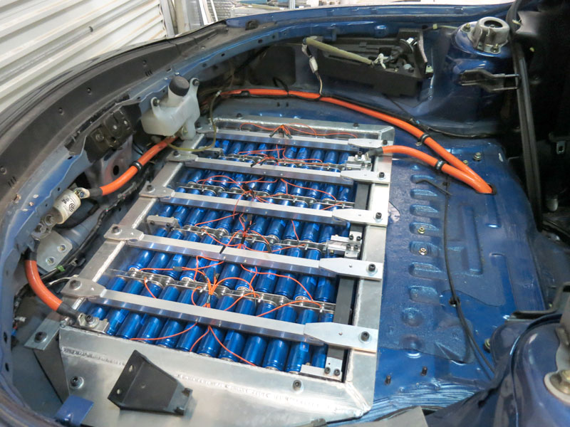
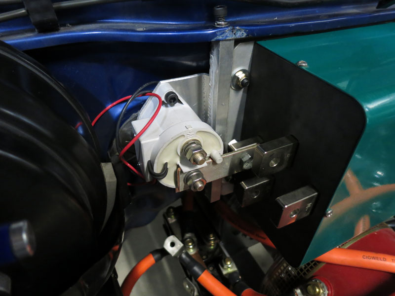
Power wiringThe first power wiring completed was on the motor assembly. The first picture below shows the position of the reversing contactor on the motor cradle. Since I'm running direct drive, reverse "gear" is achieved by running the motors backwards. With Series DC motors, you need to use a DPDT contactor to change the polarity of the field coils to achieve this. I'm using a Nanfeng ZJWH400A-2T contactor, with an extra ZJW400A in parallel with the "forwards" contacts to help cope with the very high currents the Zilla 2K controller can deliver. The next few pictures show the procedure for making power cables, for the benefit of anyone who's never done it before! Pretty straight forward: cut to length, strip a section of insulation, crimp a lug on, then add heatshrink. The difficult part is probably making sure you use the right tools, namely a good set of cable cutters and a big hydraulic crimping tool. For the latter I used a TPT Tools KYQ-300. With 16T of force and big hex dies, it does a great job of the big 95mm² lugs. (The more economical 8T or 12T crimpers are fine for the 50mm² cable, but a bit borderline with anything larger!) The final picture below shows the completed power wiring on the motor assembly. The next power wiring to be completed was the boot area, and the two cables running from the rear battery box, under the vehicle and into the engine bay. Unfortunately due to the 5-row layout of the rear box, the two end terminals are at opposite corners of the box, so necessarily one cable has to travel halfway around the box to meet the other. I also wanted a fuse and auxiliary contactor installed very close to one terminal of the battery box for safety reasons. I mounted these right at the back of the vehicle near the right-rear battery box output terminal (pictured below). Near the opposite end of the battery box, I cut a small hole in the boot floor to allow two cables to exit the boot. Whenever cables go through metal panels, it is essential to line the edges of the hole with rubber/plastic to prevent the sheet metal from damaging the cable insulation. Clark Rubber carry a wide range of C-section material for this very purpose. The final picture below shows the completed boot area power wiring. Note the cable clamps which act as strain relief for the cables before they exit the boot (available from most automotive stores, these ones are Narva brand from Auto One, very tough construction of steel with rubber insulation).
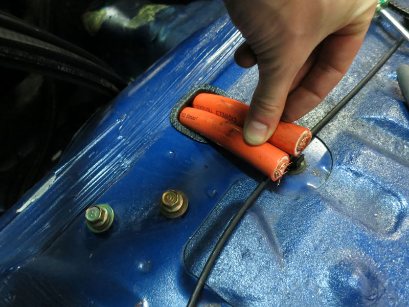
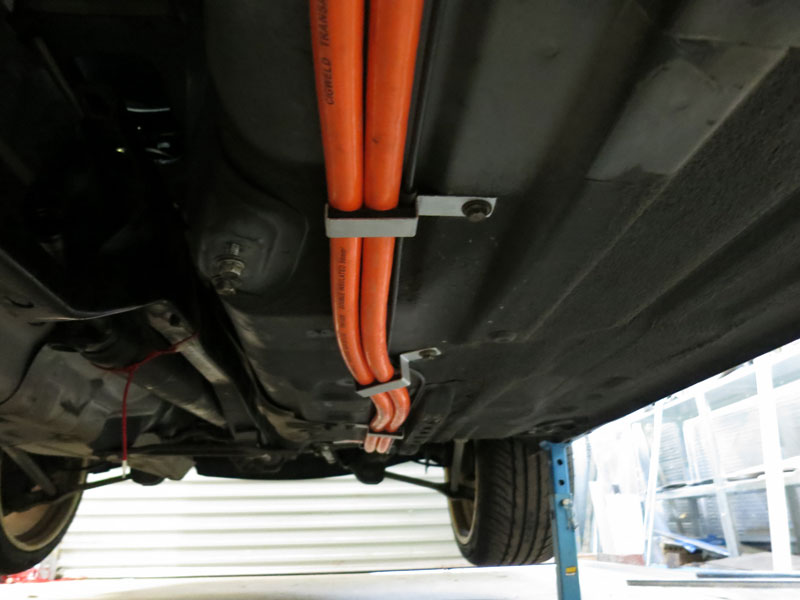
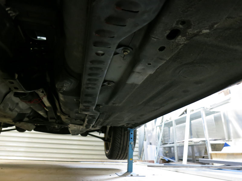
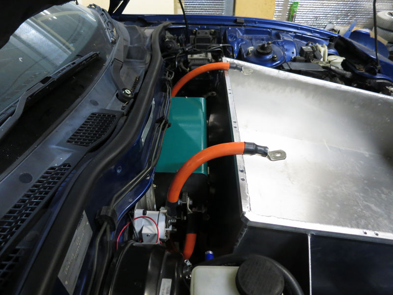
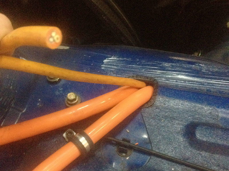
Front-rear power cablesFor any vehicles with a split pack (that is, batteries in more than one location - usually front and rear) it is necessary to run power cables between them. For a front/rear split, my usual preference is to run the cables within the driveshaft tunnel, where they are well protected. However for the RX7 I noticed that there is a protected channel next to the tunnel which previously housed the fuel lines and (still) the rear brake line, which was big enough to hold two 95mm² power cables as well as the brake line. It was too good not to use. And if it's protected enough for fuel lines, it should be fine for power cables too.
(Note: At no point are the power cables the lowest point of the vehicle - I would consider this a mandatory requirement in any EV! You can see there is a steel protrusion running adjacent to the fuel line channel which should protect them if I go over a nasty speedbump.)
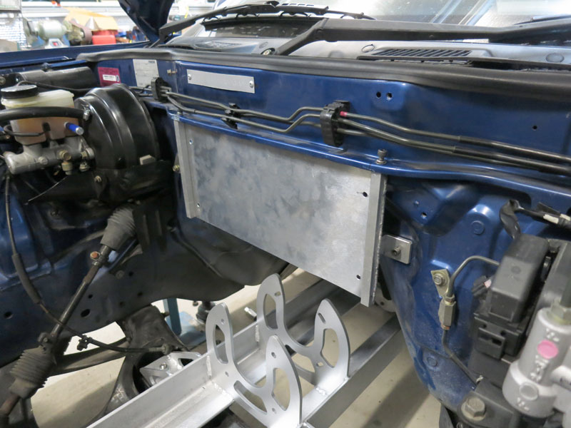
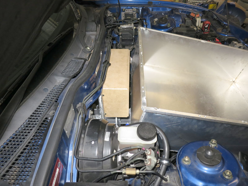
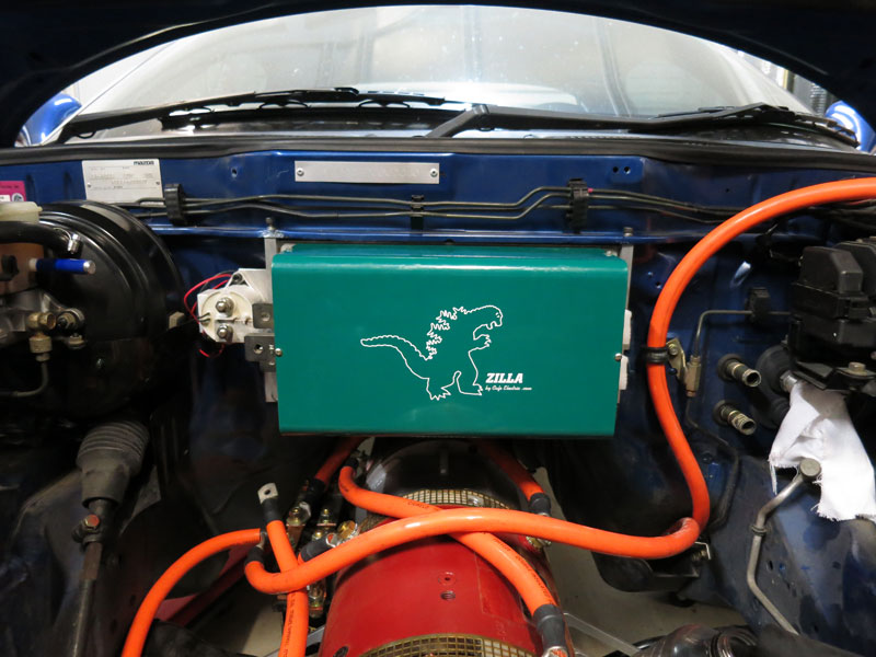
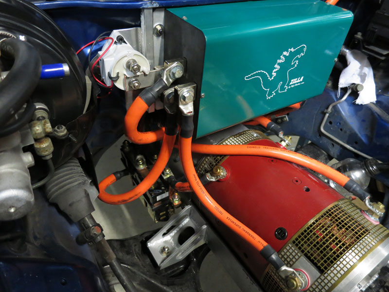
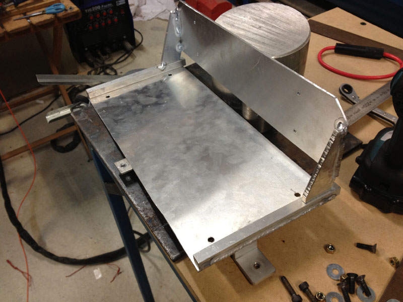
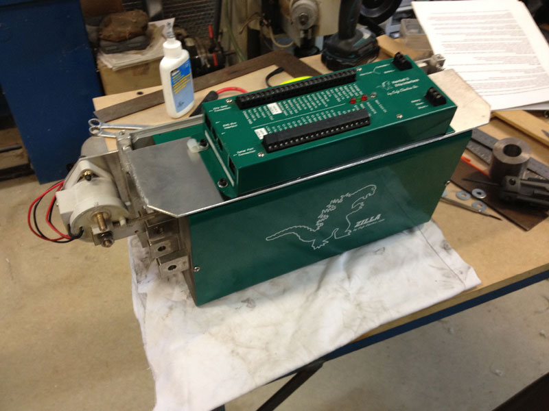
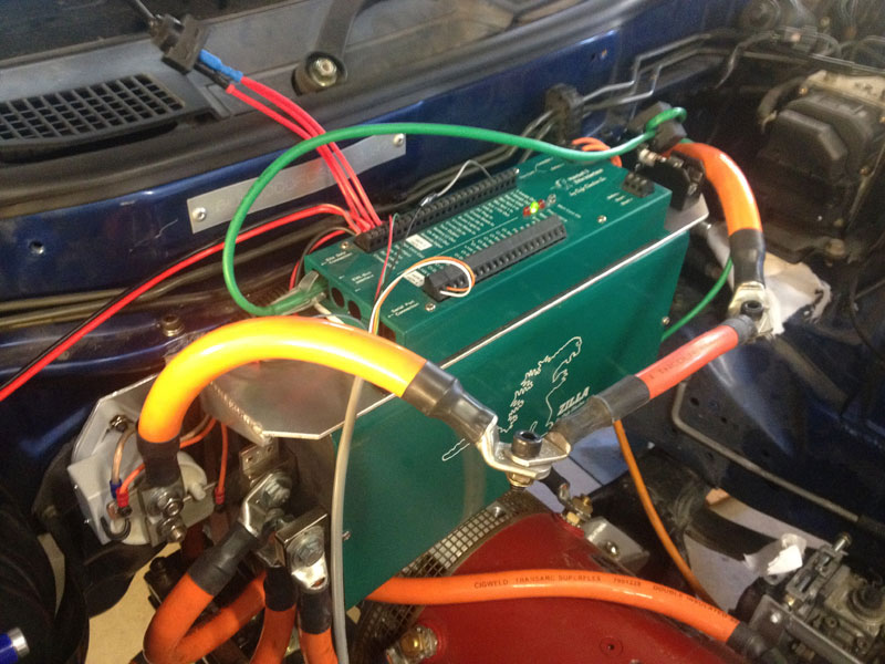
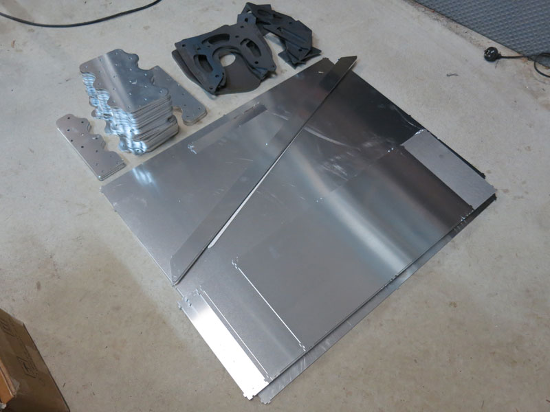
Zilla controller installationThe first task in mounting the Zilla controller was to fabricate a mounting plate, made from 3mm aluminium, with brackets/screws fastening it to the firewall in four places. Note that the motors aren't even in their cradle in the photo below! I actually made the bracket a while ago to verify that the controller would fit above the motors and behind the batteries - see 2nd photo. In the third photo you can see the real controller installed, and the Kilovac EV200 main contactor just to the left. The fourth picture shows a closeup of the contactor and its mounting bracket. Then it was just a case of making up the power cabling from batteries to controller and controller to motor(s). When designing EV conversions, I seem to have a bad habit of trying to squeeze big battery packs into small cars. Whilst it can result in good performance, it can make fitting everything else in the car a bit of a juggling act. So for the Hairball (the "brain box" for Zilla controllers), about the only good place it could go was on top of the power box. So I had to disconnect and unmount the controller and its bracket, then add an extra shelf to the bracket. The pictures below show welding extra shelf to the Zilla mounting plate, fitting of the Hairball and power box, and finally reinstallation in the engine bay. In the third picture you can also see some messy test wiring connected to the Hairball, in order to finally give the motors a test-run. It was powered just by the rear battery box (note the big jumper/bypass wire across the front battery box connections). The grey cable goes to the HEPA throttle pedal (which will be replacing my original accelerator pedal), the black/red wire (left) is supplying 12V power, the switch (top left) simulates the ignition key, and the green wire is the communications wire between Hairball and power box. (The Hairballs have a LOT of connections which can look a bit daunting at first, but you only need to use a handful of them to get things up and running.) One the test rig was finished, I flicked the switch and.. Hallelujah, the drivetrain works! But there's still plenty left to do before the car is finished..
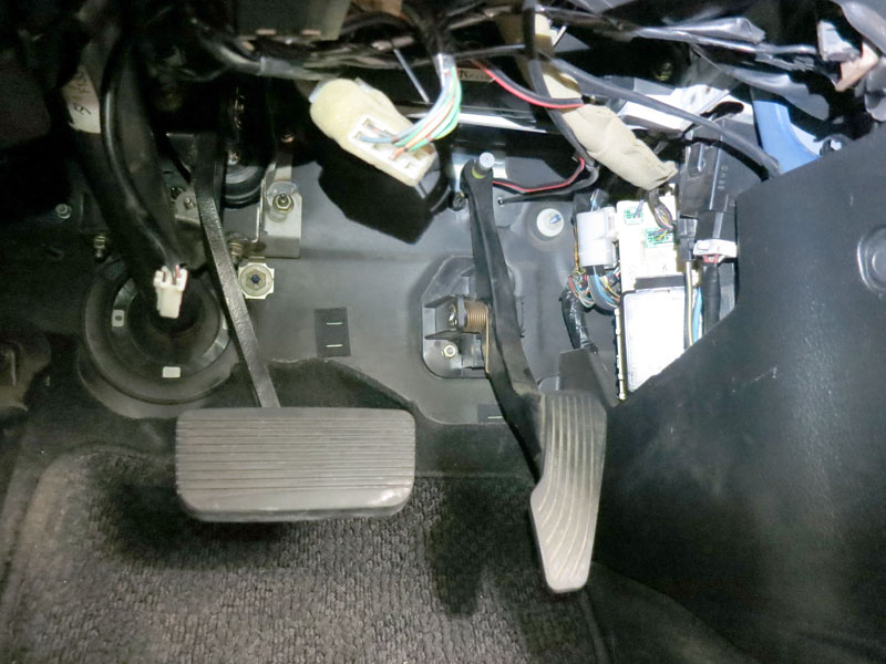
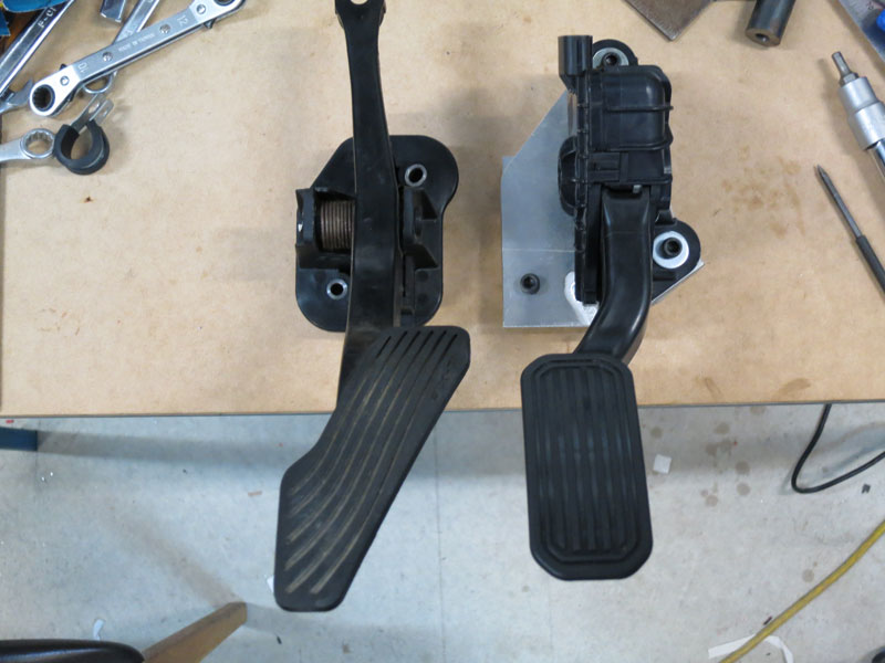
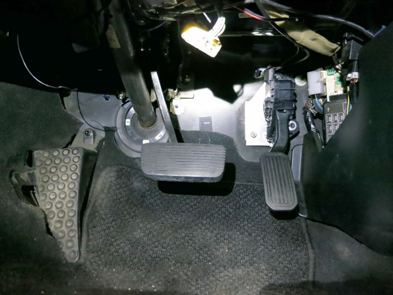
Hall Effect Pedal Assembly (HEPA) installationHEPAs are becoming the new standard in vehicle throttles. Most modern petrol-powered vehicles now use HEPAs connected to throttle servos for drive-by-wire, instead of using mechanical throttle cables. Historically, EV conversions used a throttle controller built around a single potentiometer (known as a "potbox") actuated from the throttle cable. However these potentiometers tended to get rough and unreliable over time. HEPAs offer a more reliable solution, using non-contact hall sensors for pedal angle sensing so they never wear out, and having two independent sensor outputs for redundant safety. They usually come as a complete pedal unit (rather than a "potbox" style), so the best option is to replace the original pedal with the HEPA unit. Pictured below is the original RX7 pedal in the footwell. The middle picture shows a comparison of the original pedal (left) with the HEPA unit (right). You can also see the aluminium adaptor plate I made up to convert the HEPA's mounting bolt pattern to the RX7's. The third picture shows the HEPA installed in the footwell.
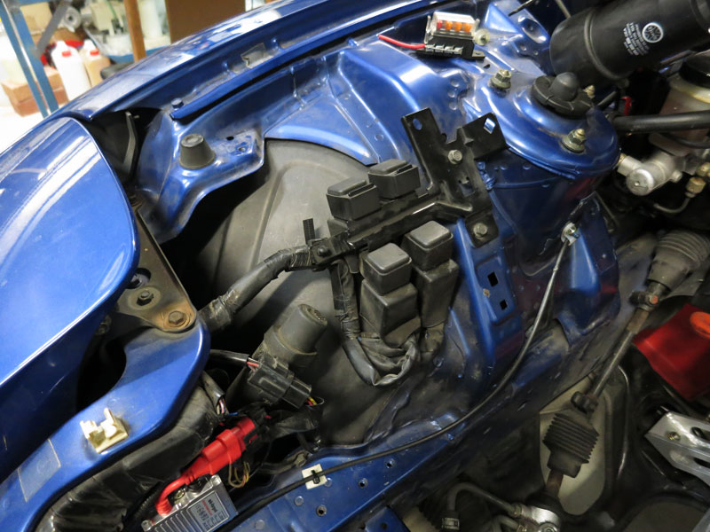
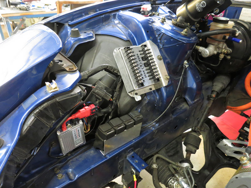
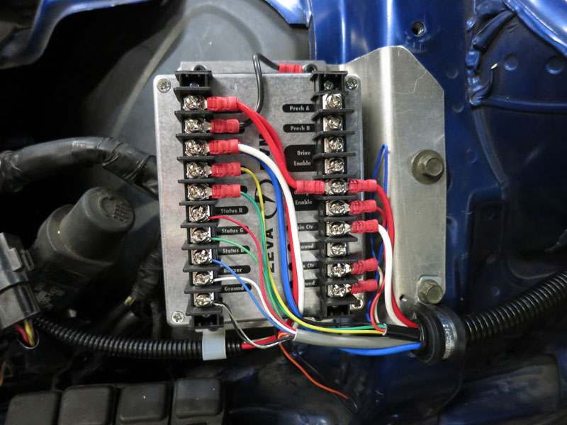
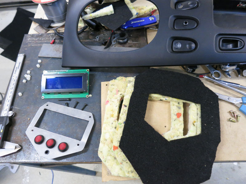
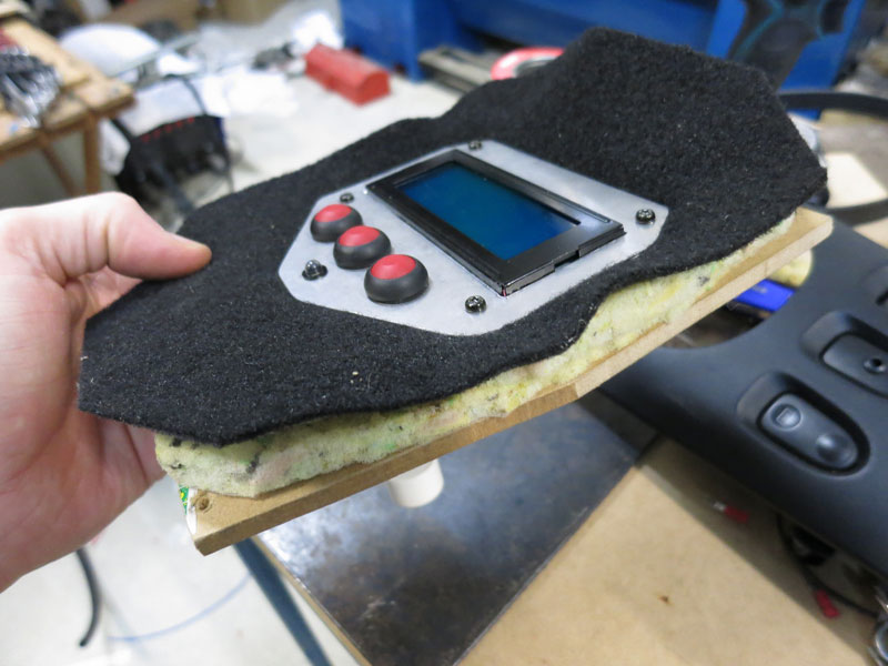
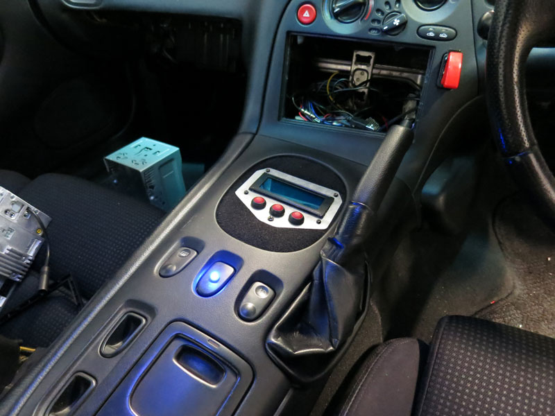
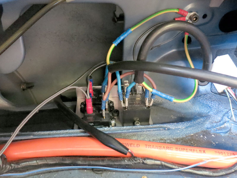
12V Control WiringThe "heart" of my 12V control wiring is an EVMS, a little widget I designed a while back which handles contactor control, interlocks, precharging (if the controller doesn't already), and BMS master functionality. As much as anything else, it's a good way to keep the control wiring neat and coherent. There was a nice spot to install it on the driver's side of the engine bay, other than having a few OEM relays in the way which were soon moved. To provide a little more detail about the EVMS wiring in the third picture above, the split conduit coming from the left is bringing permanent 12V (red) and key-switched 12V (white) from the battery. The permanent 12V also continues on to the "charge enable" relay and the Zilla Hairball. The right-hand white wire is the main contactor output, which goes to the Key input on the Hairball. The grey multicore cable connecting to several pins on the bottom left goes into the cabin to a status LED and warning buzzer. The other multicore cable (black end) goes all the way to the back of the car, with a wire for the auxiliary/rear contactor, BMS high and low voltage signals, charger detect input, and charge enable output. The Zilla Hairball handles precharge internally so those terminals and the Drive Enable relay in the top right are left unused. This current model of the EVMS uses a multicolour LED and a buzzer for status information in the cabin. I'm also working on a new model which integrates instrumentation functionality and drives an LCD display showing volts/amps/SoC/etc. In preparation for the new EVMS, I installed an LCD module and buttons on a panel in the centre console, in the big hole where the manual gear lever used to be. I sealed off the hole through the centre tunnel with a polycarbonate panel. The control panel is made of aluminium, mounted on risers to an MDF panel, which screws to the underside of the centre console moulding. There is also a surrounding of black carpet over foam baffling which fills the space around the control panel.
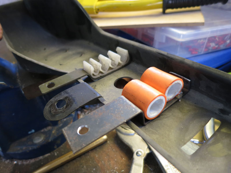
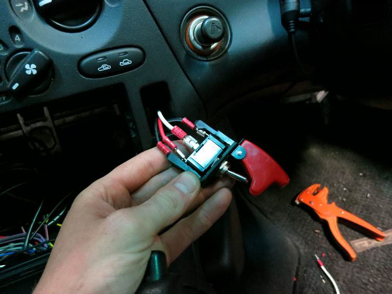
Reverse switch
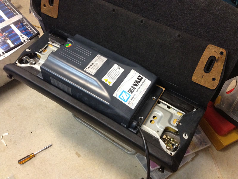
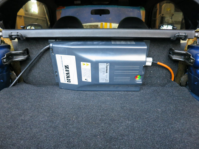
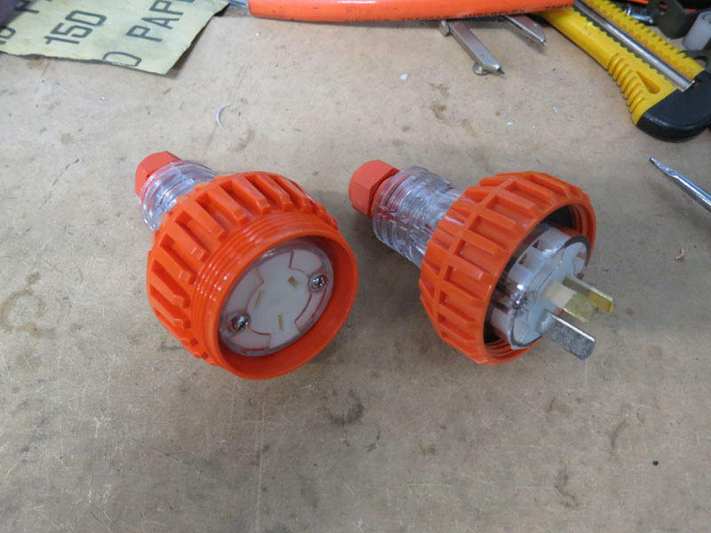
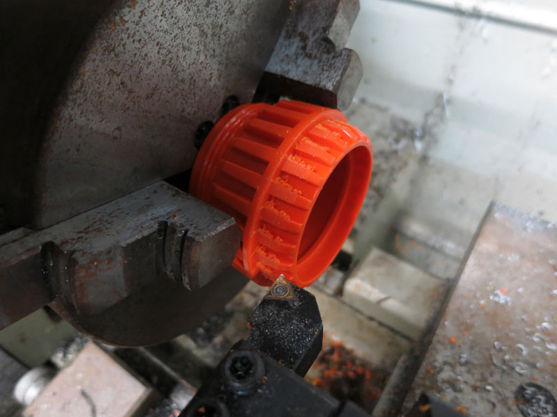
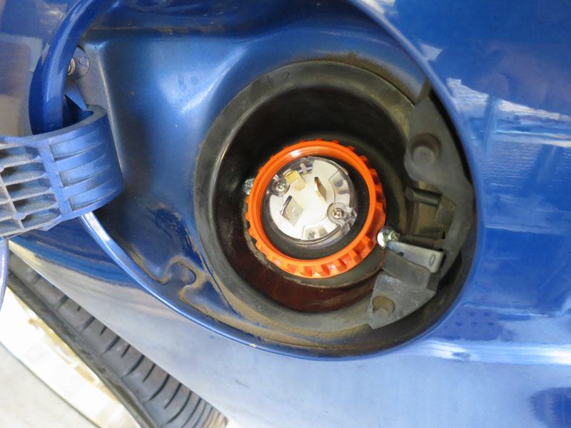
Charging SystemFor charging, I chose a Zivan NG3 288V. Zivan is an Italian company who've been making chargers for a long time. They're not cheap (about twice the price of many Chinese manufacturers) but are a reliable and well-proven charger. They're not especially weatherproof so I prefer to install them inside the vehicle cabin. In this case, I attached it to the back of the rear seat, as shown in the pictures below. The 288V NG3 has an 8A DC output, so it doesn't require particularly heavy-gauge wiring to the battery pack. To connect the charger (in the back) to the HV terminals (up front) I used a length of orange 240V 15A 3-core cable from an old extension lead, installed in the same channel that carries the main power cables. On the AC side, as usual I elected to install the charging plug behind the fuel door. For reliability and "weatherproof-ness", I purchased male and female weatherproof Clipsal 240V 15A plugs which screw together to form a waterproof and secure connection. With a little trimming down in the lathe, the orange shroud slid in nicely to the existing hole inside the fuel door.
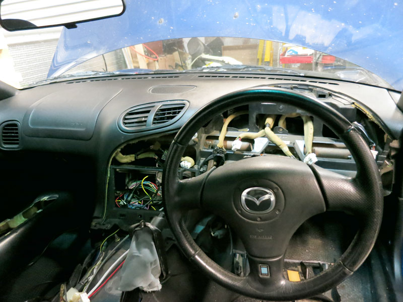
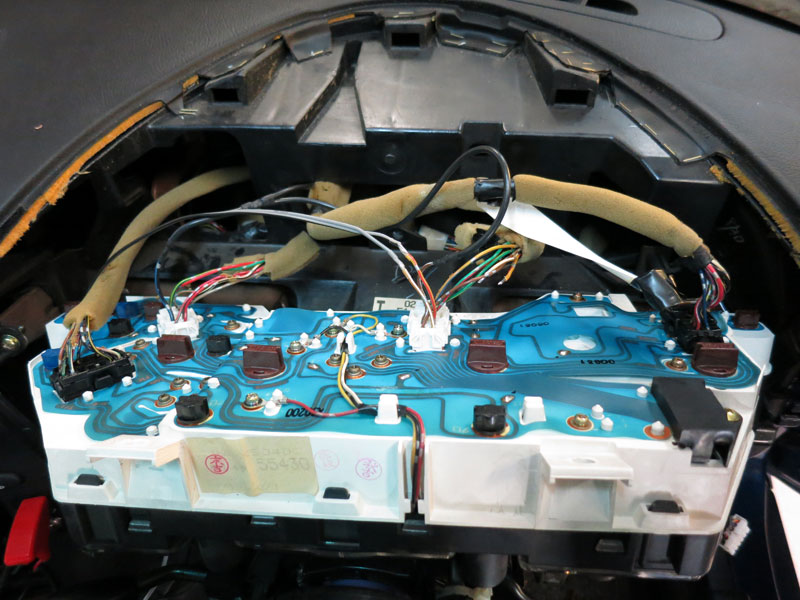
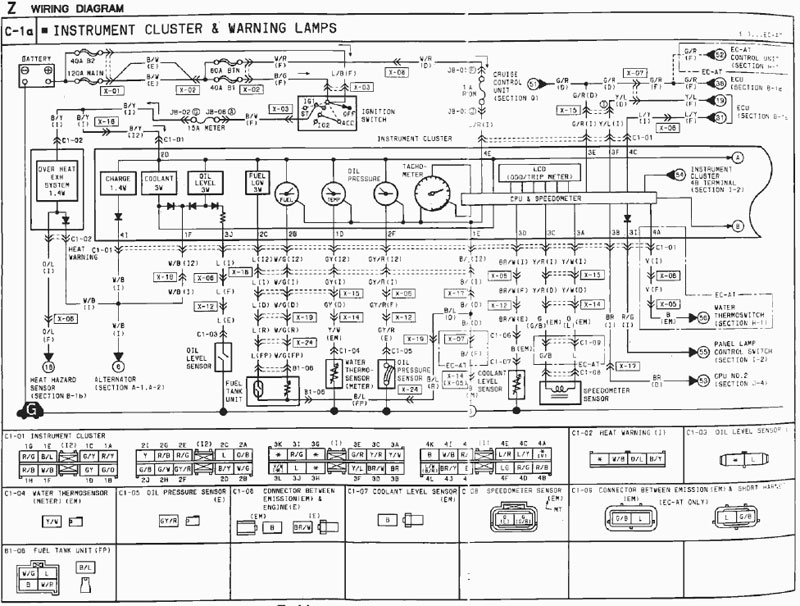
Instrument ClusterOne of the most difficult and frustrating parts of an EV conversion can be convincing the original electronics to "play nice" with the new EV drivetrain. This is particularly so with modern vehicles which usually have many onboard computers and communicate in proprietary protocols over a CAN bus. In fact I would recommend avoiding such vehicles for conversions, and it's a good reason to choose slightly older donor vehicles! The RX7 doesn't have CAN bus but does have several computers, and when the ECU and its associated wiring harnesses came out, it caused a few problems. The most problematic was the instrument cluster stopped working - including the (digital) odometer and speedometer. There are about 50 wires that go to the instrument cluster so diagnosing it without workshop manuals would have been virtually impossible. Fortunately I managed to find workshop manuals online, albeit for an older model (1993 instead of 2000). The Series 8 was never sold new outside of Japan so (AFAIK) there are no English workshop manuals in existence. Fortunately the Series 6 wiring is *fairly* similar. I've uploaded them here for anyone else working on an RX7: The other useful file I found online was a pin-out list for the series 7/8 ECU, which did change a lot since the Series 6 described in the above manuals. Click here to download the ECU pin-out. After a great deal of investigation and hair-pulling trying to figure out why the instruments weren't working, I finally managed to solve it with the following steps: (I've included colour codes and pin identification for anyone repeating the process!)
For now only the essentials work (speedometer and odometer), but I plan to reuse some of the other gauges in future to display meaningful EV information. I'll use the fuel gauge for battery state of charge of course, the tachometer to display (hundreds of) amps, and the temperature gauge to show motor temperature.
Continue reading --> Auxiliaries
Comments
|
||||||||||||||||||||||||||||||||||||||||||||||||||||||||||||||||||||||||||||||||||||||||||||||||||||||||||||||||
Zero Emission Vehicles Australia © 2026 :: Terms and Conditions, Privacy Policy, Payments and Delivery, Warranty and Returns