
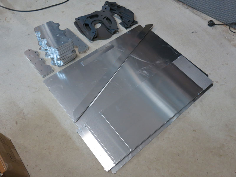
DrivetrainGearbox Adapter Plate
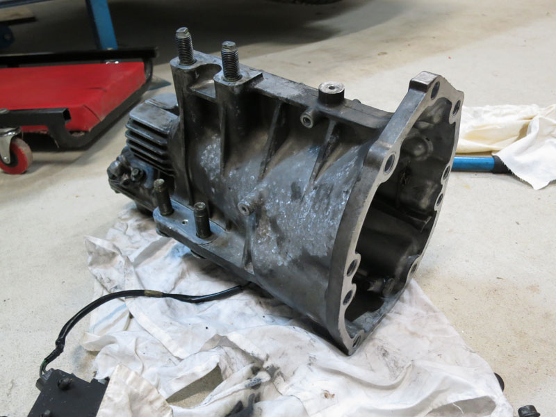
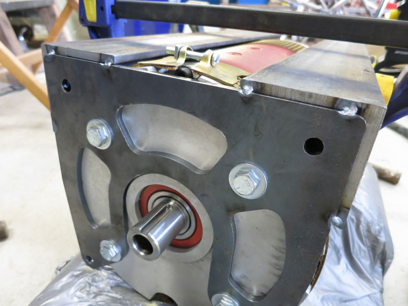
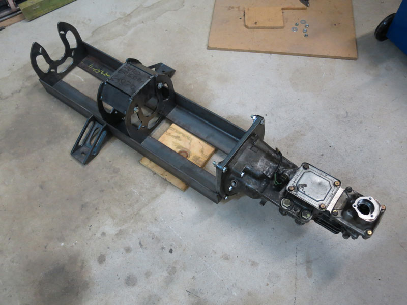
Firstly for the gearbox adapter plate, which fits between my motor cradle and the gearbox end section (which I am using for its speedometer sensor, and accurate tailshaft / torque tube alignment), I only had the basic shape laser cut. I then got High Speed Engineering to digitize the bolt pattern of the gearbox piece with respect to its tailshaft output, and used a milling machine with digital readout for precisely drilling the holes. The gearbox end section has a couple of 12mm dowel pins for accurate positioning, and half a dozen 12mm holes for M12 bolts, which fasten into threaded holes in the 12mm thick adapter plate.
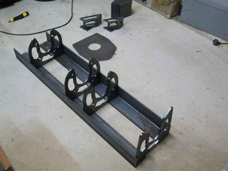
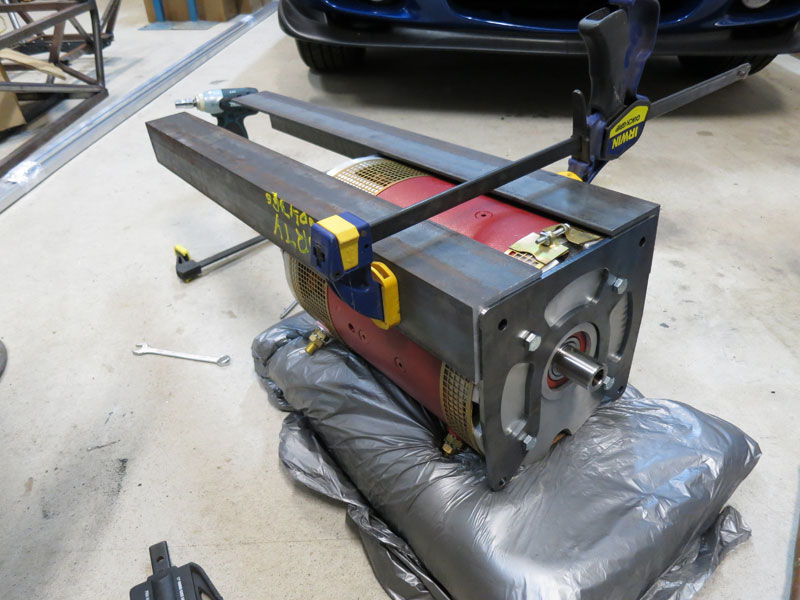
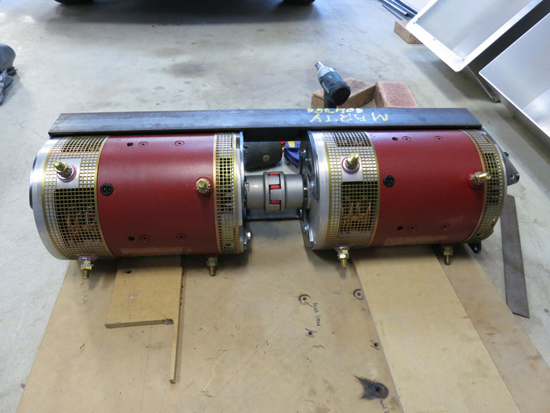
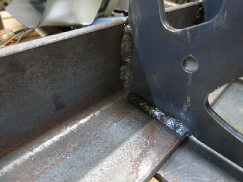
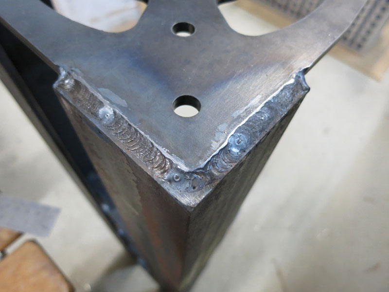
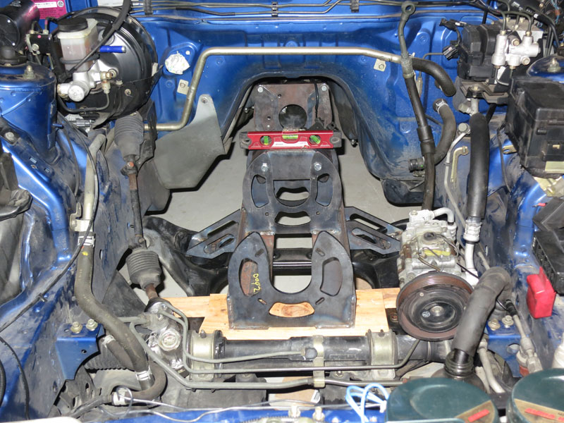
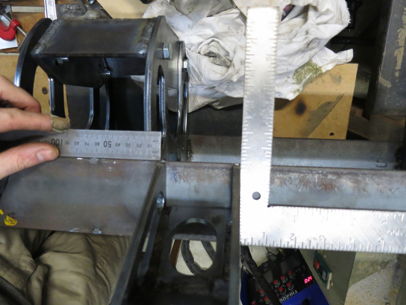
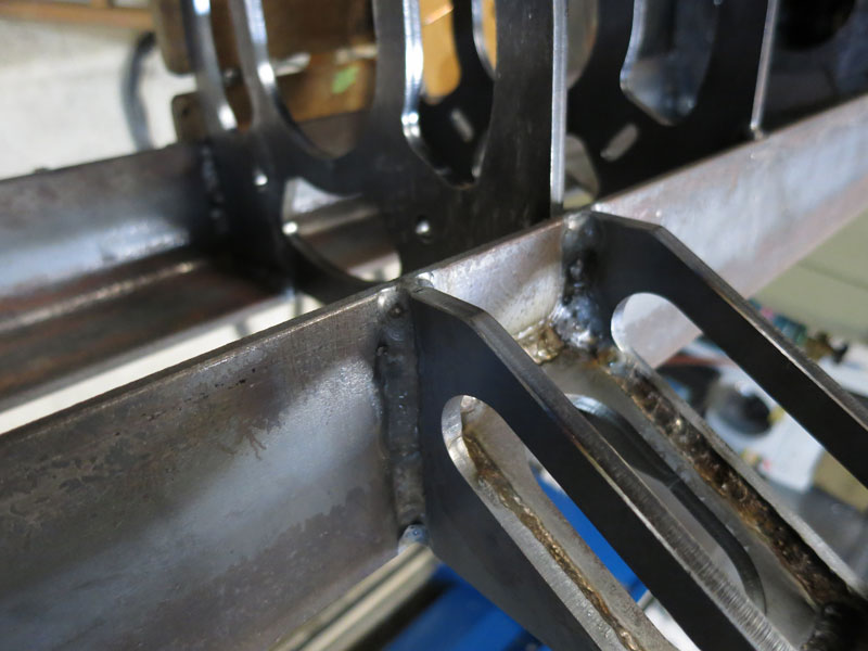
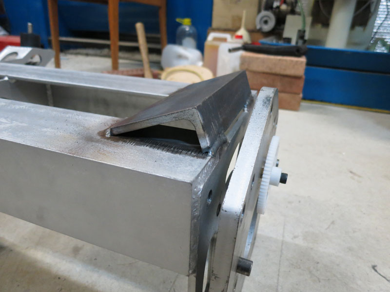
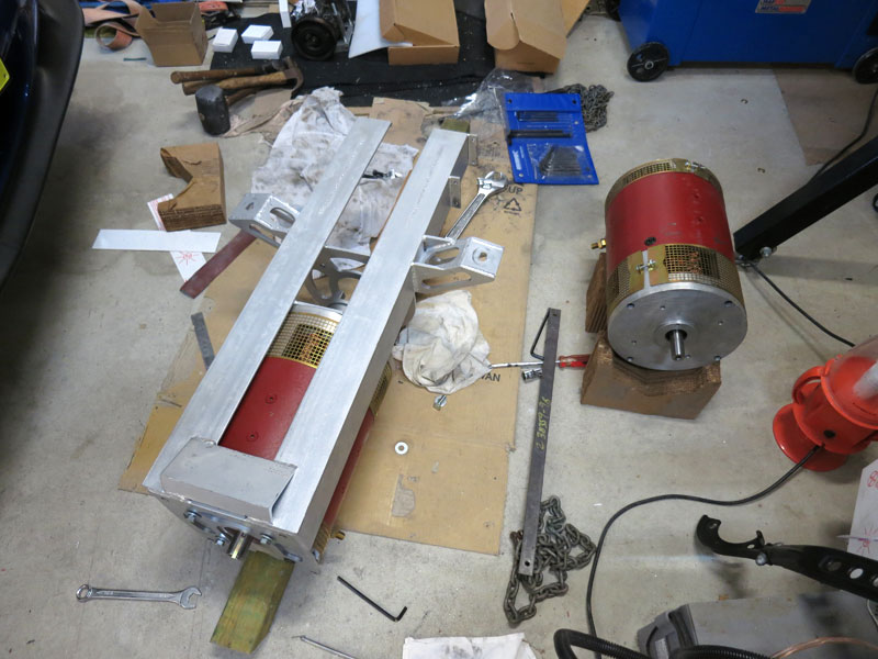
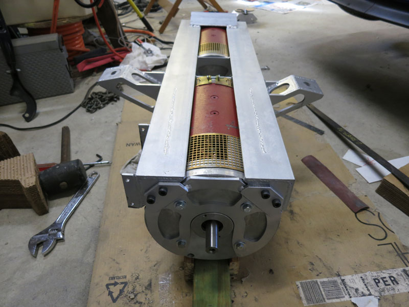
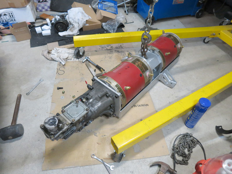
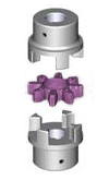
Motor Cradle AssemblyI decided the best way to construct the motor cradle accurately would be to tack weld it together around the motors, then do final welding without the motors (so they don't get too hot, or get in the way). The pics below show test assembly of the pieces, clamping them to one of the motors, and tack welding them in-situ. Once the frame was tack welded together, I did a test-fit of both motors including Rotex coupling, to verify both fit and alignment. I then tack welded together the two "legs" which support the cradle upon the original engine mounts, and the central brace which improves rigidity between the motors. The third photo shows the assembly including the gearbox end section. (At this point the legs are just sitting in place, not actually attached.) Next I completed the final welding of the central frame section (a couple of pics showing the welding below). For welding I use a 200A TIG, which is probably slower than MIG (or stick) but tends to offer the neatest welds - and arguably strongest. I also did the final welds of the support legs - still separate from the rest of the cradle - then installed the pieces in the car and measured/marked the locations. The following three pictures just show tack welding then final welding of the support legs on to the rest of the frame, then another test fitting of the motor cradle in the engine bay. It fit perfectly - phew! (NB: You can't seem the in the photo, but there are large rubber vibration absorbers between the cradle legs and the chassis mounts.) One caveat worth mentioning .. As it turned out, presumably due to a tiny amount of distortion from welding, the motors were just too tight a fit to get back into the cradle after final welding! Not good. I ended up having to shorten the motors by about half a millimetre. Doesn't sound like much, but with such a rigid frame it made all the difference between fitting and not fitting. Shortening the motors slightly actually wasn't as hard as it sounds. I just had to remove the commutator-end casting from the motors and trim the inner side of this in a lathe. Anyway, if I built another I'd be sure to put in half a mm of shim when doing the initial tack welds, for a small amount of tolerance/clearance.
Motor/Tailshaft Coupler
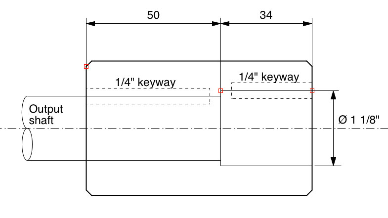
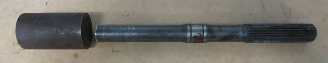
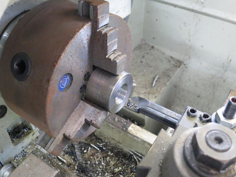
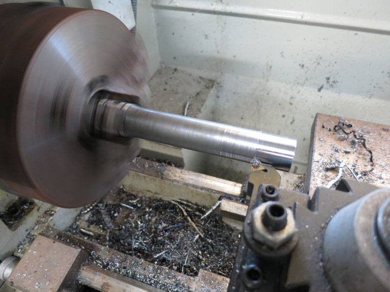
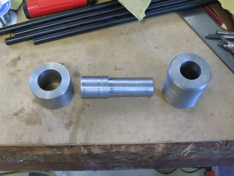
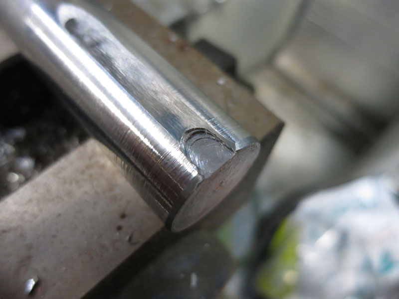
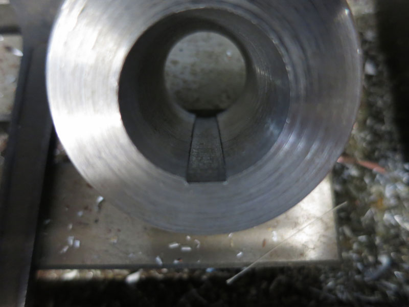
Since I have neither a broaching machine for cutting internal keyways, nor a great deal of confidence in my ability on a lathe to make something like this accurately, I was going to outsource its fabrication. But after speaking with Kim at Wattle Grove Engineering, who explained how I could do internal keyways on my lathe, and suggested a method of making the coupler in two parts and welding together, I thought I might give it a go. Good practice/experience if nothing else. Firstly, inside keyways can be done on a normal lathe by locking the chuck in place, using a boring bar with tool steel the size of the keyway, running the boring bar back and forth manually using the carriage, taking tiny incremental cuts by moving the cross slide slightly after each pass. As for the fabrication, he suggested making the coupler in two halves, which makes it easier to cut the keyways (since the larger one wouldn't be butting up against a shoulder its inner end), and cutting a big chamfer where the two meet for a nice deep weld groove. Then machine an insert which fits inside both halves exactly to hold them in precise alignment during welding (and while cooling after). However the next steps did not go so well. My mill's cutting tools had a great deal of trouble cutting a keyway into the gearbox output shaft (other than the first few MM, which had probably lost its temper when the friction cutter did its work). And the system of cutting an inside keyway on a lathe using a boring bar and the carriage was painfully slow. So in the end I got Luke at EV Works to do the coupler for me. Oh well, at least I tried.
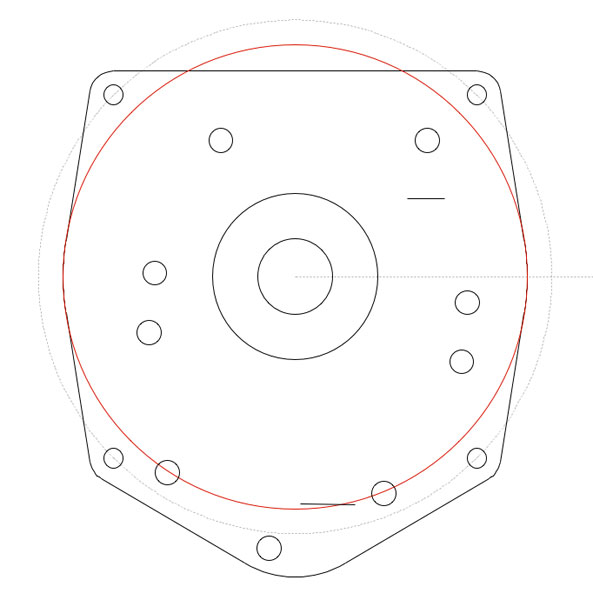
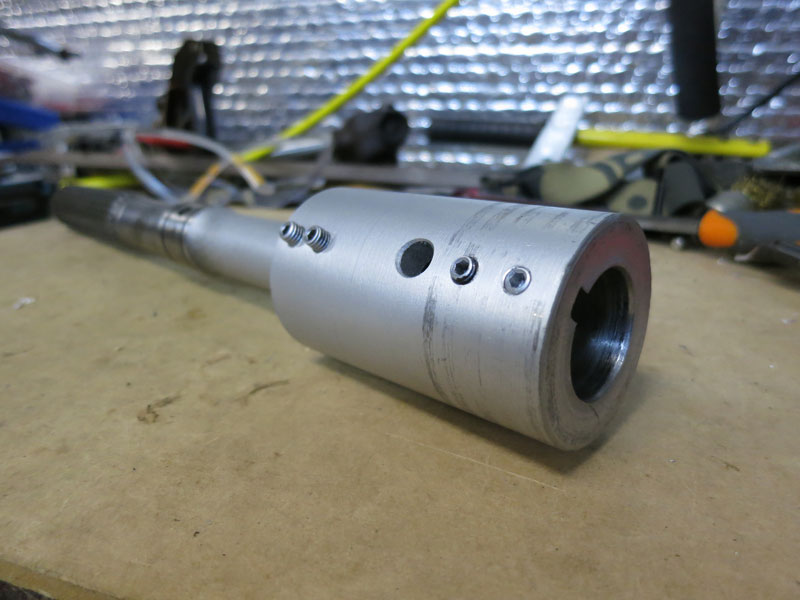
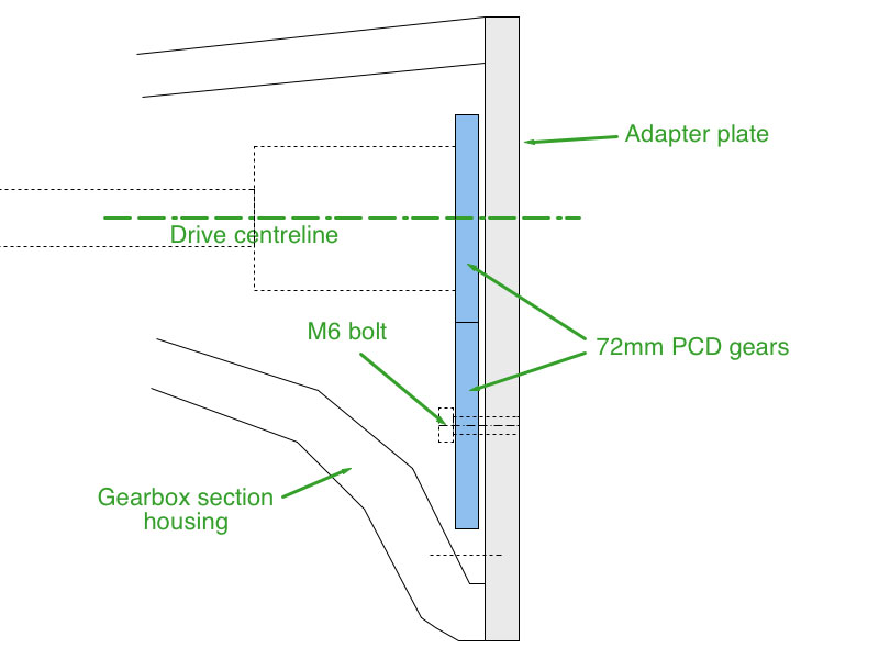
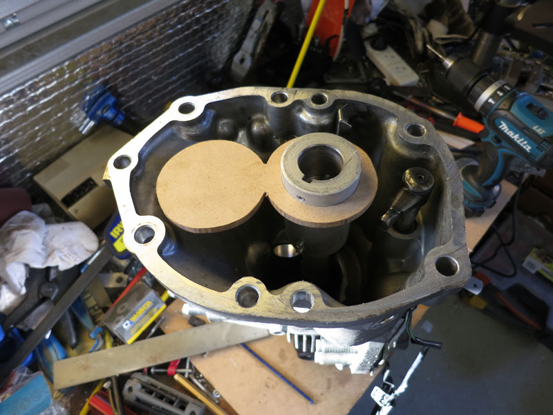
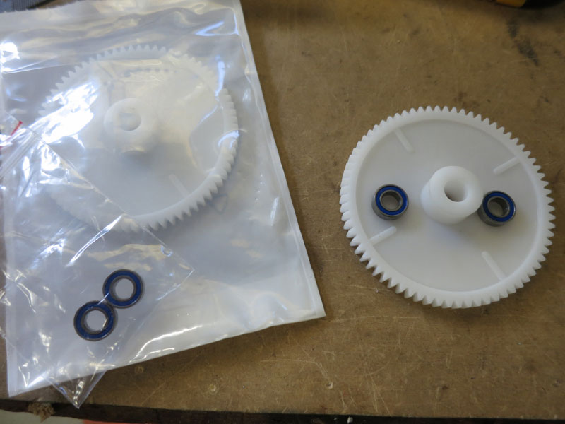
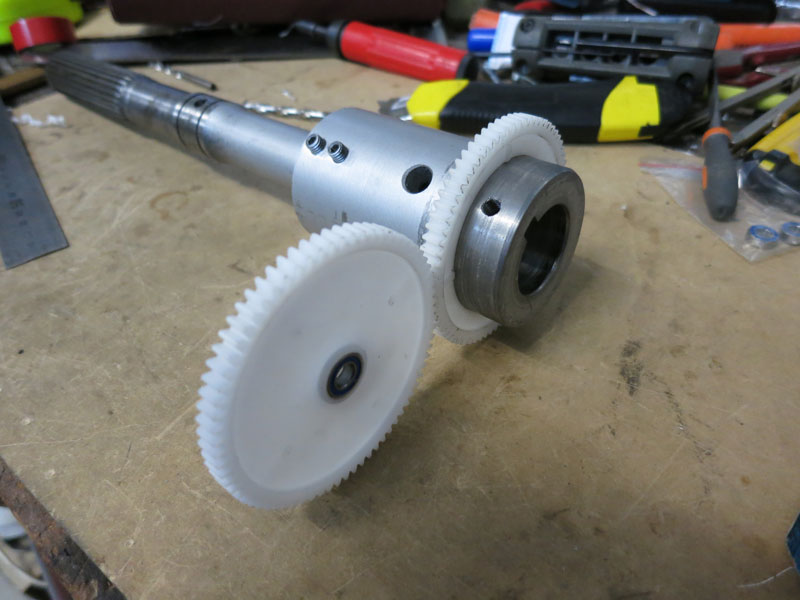
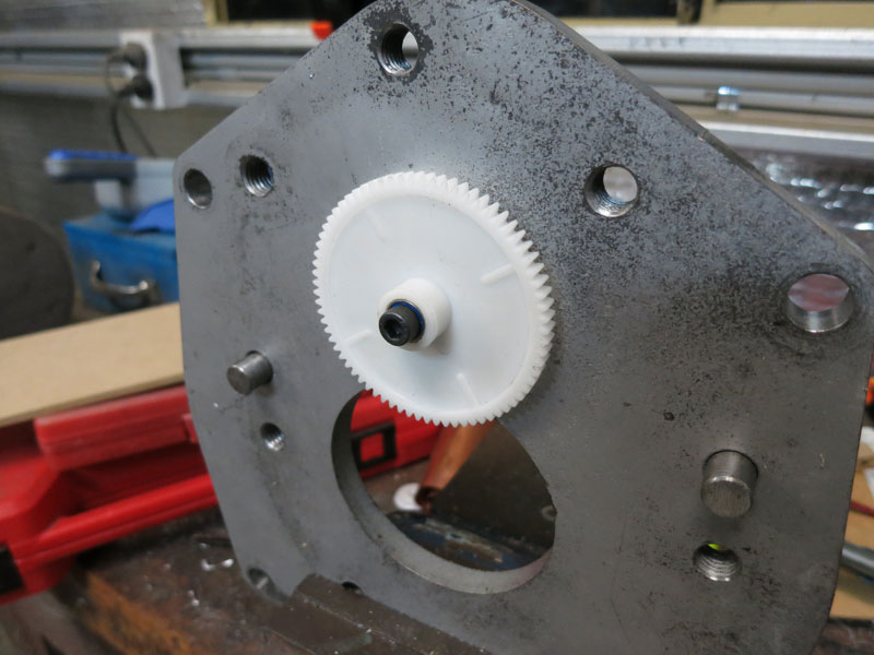
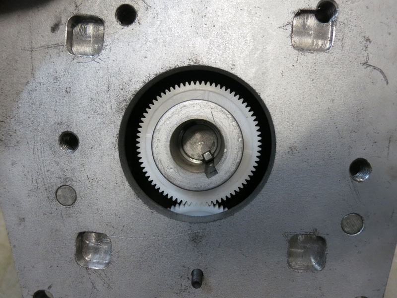
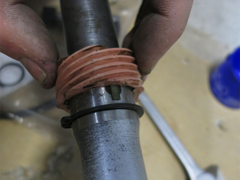
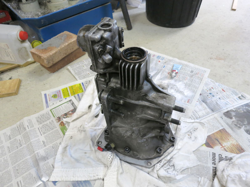
Oil Circulation for Tailshaft BushingThe gearbox end section has a bushing which the tailshaft slides into. This is intended to be lubricated with gearbox oil, and includes a channel to carry oil to it. But since I'm only using the end section, there wasn't necessarily any oil in there - and the bushing would probably overheat without it (making it squeal and wear out at best, or seize up at worst). I considered modifying the end section to use a ball bearing instead, but it would actually be a fair bit of work chopping the bushing off, fabricating a bearing mount, and ensuring the alignment remained perfect. So I decided the best option was to add some oil, and a means of throwing the oil into the channel which runs down to the bushing. (Some people had suggested that with enough oil in there it would slosh back to the bushing whenever I accelerated, but I was still concerned about the bushing drying out with extended highway use at steady speed.) After a bit of pondering, I decided on a couple of gears, one mounted to the driveshaft coupler and another below, with its teeth picking up oil off the lowest part of the gearbox section. Below you can see my initial sketch based on measurements of the gearbox section, then a 1:1 wood mockup I made to verify the fit. A couple of plastic gears were procured from RS components - the third picture shows these, and some 12x6 bearings for mounting the lower gear. Below you can see the modified gears, one with bearings added and the other a press fit engaging onto a small shoulder I machined into the driveshaft coupling. The gears aren't really taking any torque so I figure an interference should suffice. I then carefully drilled and tapped a threaded (M6) hole into the adapter plate, and fastened the idler gear on. In the third picture you can see the alignment of the gears verified.
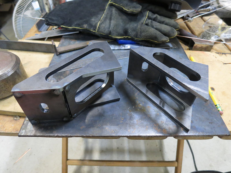
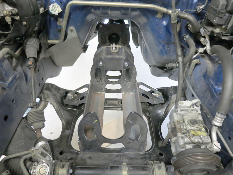
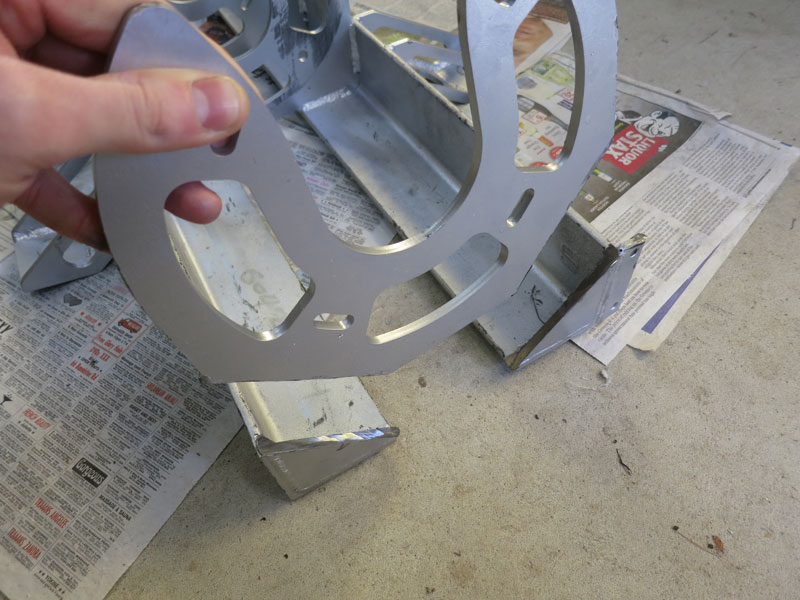
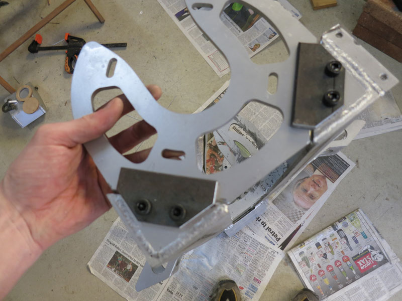
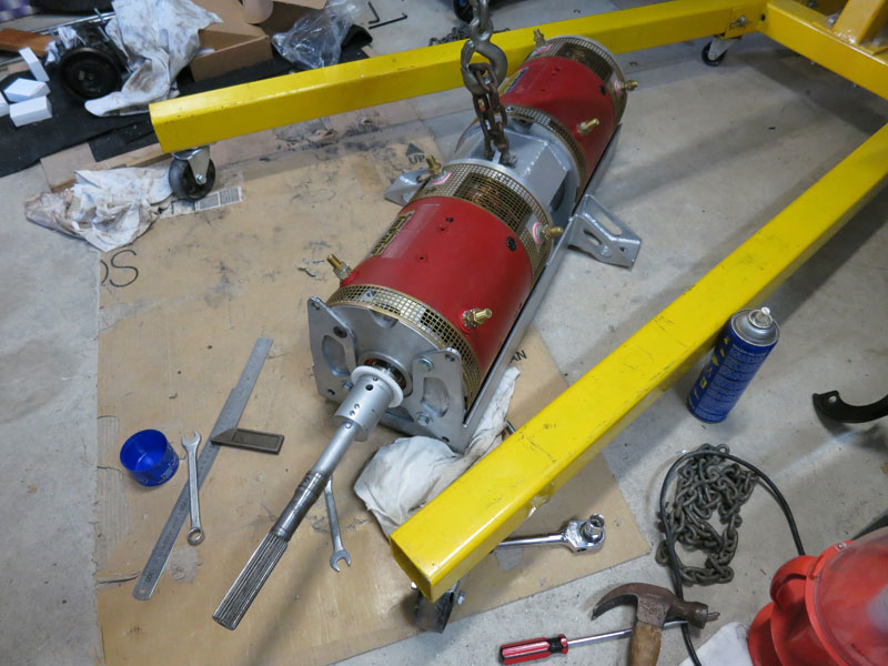
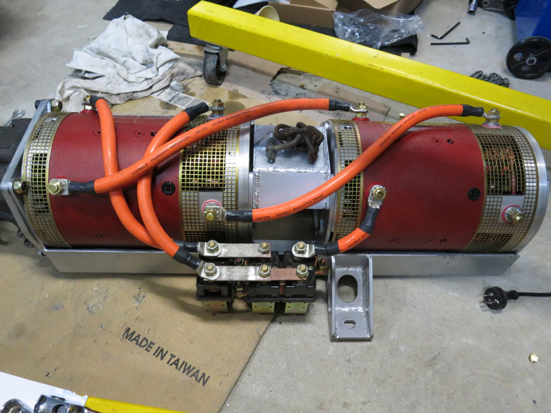
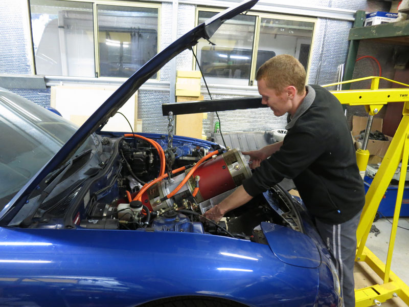
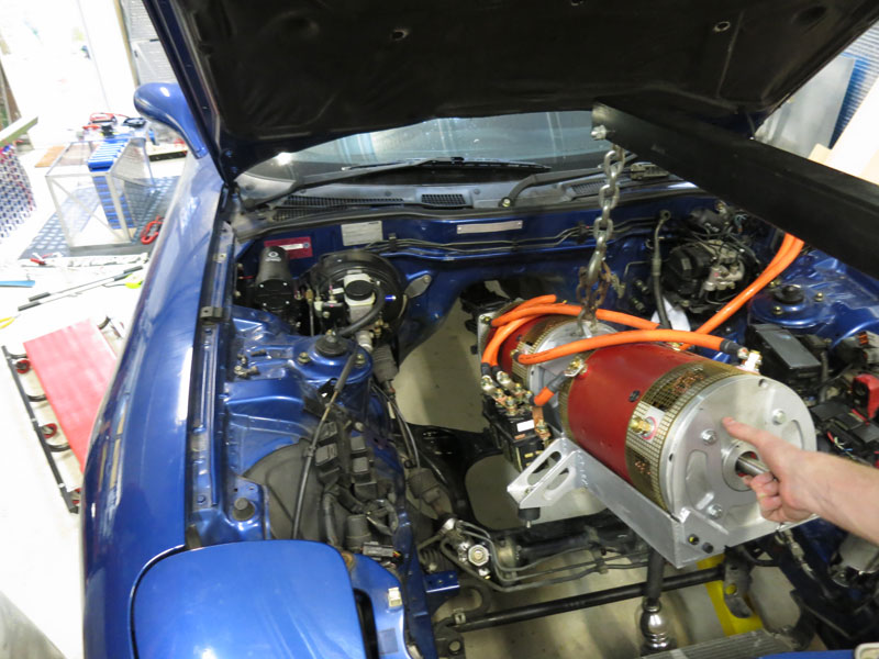
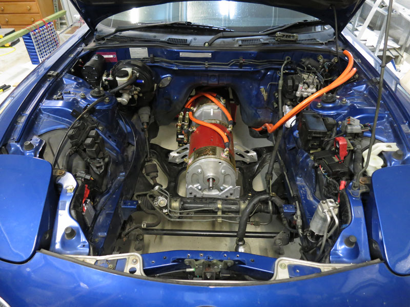
Installing The Motor AssemblyThe way the motor frame was originally designed left me no choice but to install both motors simultaneously. After spending an infuriating hour or two trying to get the motors in, I came to the conclusion that maintaining simultaneous perfect alignment of two heavy motors in such a tight-fitting frame was not going to happen. So I modified the frame to allow the motors to go in one at a time. A few minutes with the angle grinder had the front end plate of the motor frame removed as per the first picture below. I then made up a couple of mounting tabs which were welded to the end plate, and screwed in to the rest of the frame. With this end plate removable, I could install the rear motor first then front motor, separately. The other final modification I made to the frame was to add a skid plate / bash guard, to protect the adaptor plate (since it extended below the main motor frame rails by a few centimetres, and I was concerned it could catch on something and be damaged). The three pictures below show the installation of the rear motor first (inverted and attaching frame onto motor, since the latter is much heavier and harder to maneuver), then installing the second motor, then after installing the central brace and righting the assembly with an engine crane, tapping on the driveshaft coupler. Before the gearbox section could be installed, I put the speedometer drive gear back on (first picture below). Then I fastened the gearbox section to the adapter plate (second picture), and then bolted these up the the motors (third picture). To my great relief, the alignment appeared to be perfect, without any tight spots as I turned the central Rotex coupler by hand. Phew!
Continue reading --> Battery Packs Comments
|
|||||||||||||||||||||||||||||||||||||||||||||||||||||||||||||||||||||||||||||||||||||||||||
Zero Emission Vehicles Australia © 2026 :: Terms and Conditions, Privacy Policy, Payments and Delivery, Warranty and Returns