
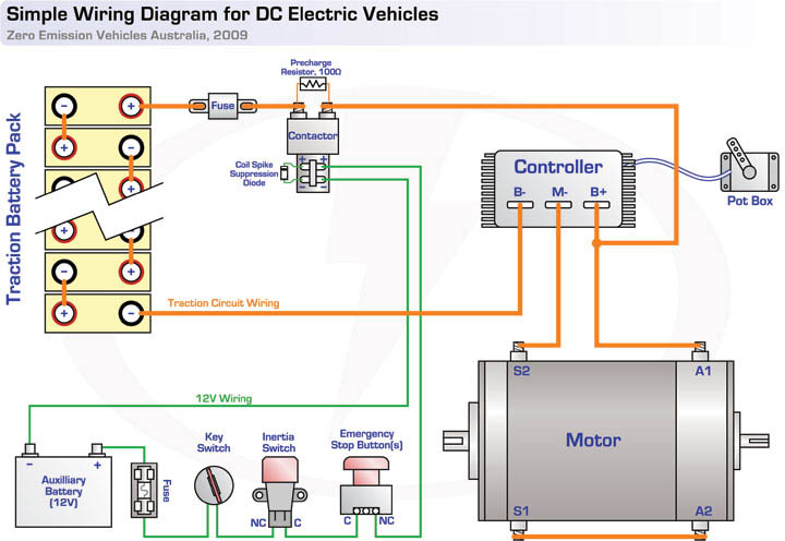
The diagram above shows the "bare bones" wiring for the traction circuit in a typical electric vehicle, with a series DC motor and controller.
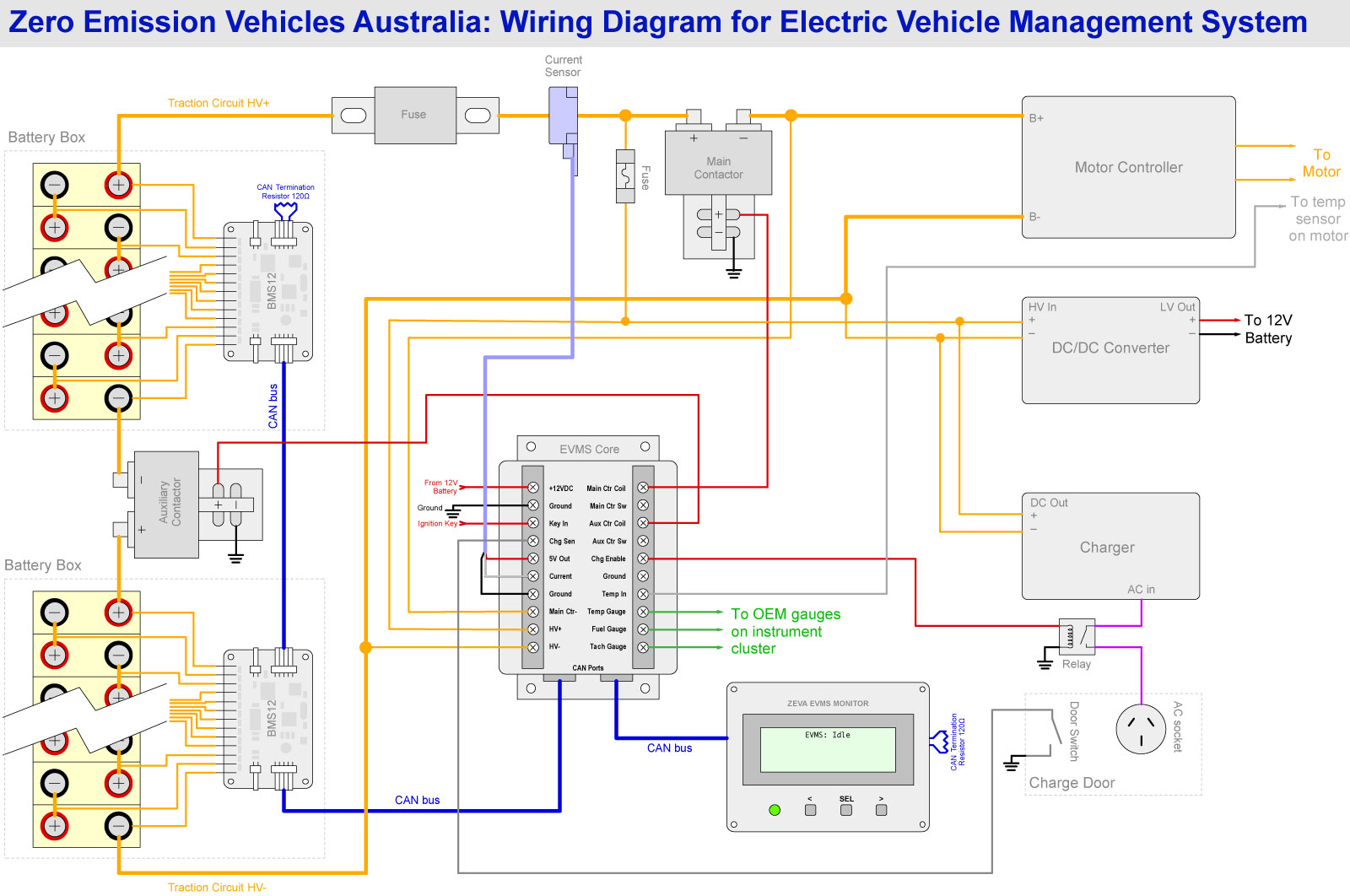
Next, here's a more complex diagram showing the typical wiring for our Electric Vehicle Management System. It also demonstrates the wiring for battery management modules, the way to connect split battery packs with mid-pack break-up contactor(s), where to wire in your DC/DC converter and charger, and how to safely integrate your charger with the EVMS for over-charge protection. Click on the preview below for an larger view. The diagram may look a little intimidating at first, but should be easy to follow and become clear as you wire up your own EV.
Note that this diagram does not include inertia switch (crash sensor), which should be installed between the 12V battery and the EVMS Core's 12V supply. You will also usually need to use the key signal to switch a relay for powering auxiliary devices you may have such as brake vacuum pump, power steering pump, water cooling pump, etc. Safety note: Make sure the wiring going to your charger, BMS master, DC/DC converter (etc) is all fused appropriately for the wire gauge and voltage. This also applies to any devices you add to your 12V system such as vacuum pumps or electric power steering pumps! |
|||||||
Zero Emission Vehicles Australia © 2026 :: Terms and Conditions, Privacy Policy, Payments and Delivery, Warranty and Returns