|
 | WA EV Trial: Ford Focus Conversions |  | Ian Hooper, 18 July 2011 | | Introduction
Over the last century, petroleum has been the primary energy source powering humanity’s transport needs. However health and environmental problems resulting from pollution in vehicle emissions has long been recognised as a harmful consequence, and more recently the threat of climate change due to anthropogenic carbon dioxide (CO2) emissions – of which a large portion comes from transport – has created an urgent need to develop zero-emission transport solutions.
Why Battery Electric Vehicles?
There are many possible candidates to lower transport-related CO2 such as hybrid systems, natural gas, hydrogen fuel cells, or biofuel. However Battery Electric Vehicles (BEVs) are considered the most promising candidate for urban transport requirements, since they offer the highest system efficiencies and represent a true zero-emission solution when charged from renewable sources. |
|
The biggest hurdle for BEVs has always been driving range per charge, and the need for improvements in battery technology has long been recognised (Cairns 1992). Even with state-of-the-art batteries, electric vehicles typically have a far shorter range than petroleum-powered vehicles. Most recently-announced production EVs such as the Mitsubishi iMiEV and Nissan Leaf are stated to have driving ranges of 100 miles (160km).
With a range so much shorter than petrol vehicles, combined with charge times much longer than filling a petrol tank, EV owners need to develop new habits in their driving patterns, such as regular charging. Widespread EV adoption will also be supported by creation of charging infrastructure, to allow for opportunity charging.
Vehicles with a conventional Internal Combustion Engine (ICE) may be converted to electric drive by removing the engine and replacing it with an electric motor. For the WA EV trial, all electric vehicles involved are conversions. The primary reason for this was simply that no mass-produced EVs were available in Australia at the time.
There are, however, several advantages conversions have over production electric vehicles. They have a much shorter development cycle, since only a fraction of the vehicle is being modified. And in the case of converting pre-owned vehicles, they represent a much lower embedded energy than a whole new vehicle, and the potential to be much lower cost. As fuel prices increase and ICE-powered vehicles become more expensive to run, EV conversions may be a viable option for many vehicles on our roads.
About the WA EV Trial
The goals of the WA EV Trial is to see how EVs with an inherently limited range and several hours recharging time can be effectively used by ordinary drivers in a typical company fleet scenario. With the release of electric cars to the consumer market by all major car manufacturers being imminent, it seemed important to get a trial underway before larger numbers of EVs will be present on Australian roads. The WA Department of Transport is looking at planning issues, while the Royal Automobile Club (RAC) is concentrating on roadside assistance matters as well as on servicing issues, both being major RAC areas of business. This includes looking at service issues as well as safety issues, e.g. servicing high-voltage EVs and precautions necessary for high-voltage EVs being involved in road accidents.
The WA EV Trial also ties in with Australia’s First EV Fast-Charging Network Trial, directed by UWA/REV and funded through an ARC Linkage Grant with several partner companies. Only Level-2 charging stations are being used for this trial, cutting down the standard charging time by more than factor three, while all EV conversions have been equipped with multi-mode chargers, allowing Level 1 (slow home-charging) as well as Level-2 fast charging from either single-phase or three-phase sources.
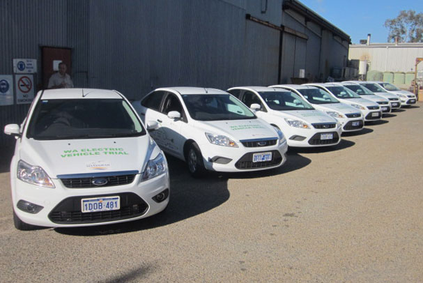
A compromise had to be reached for the base car. The participants considered the already-proved Hyundai Getz EV to be too small, while the authors considered the participants’ suggestion of a Holden Commodore as too heavy. Finally, both sides agreed on a Ford Focus Sedan as a middle-sized trial vehicle and the target range of 120km on a single charge has been agreed on as the main performance characteristics. After building and accepting a single prototype conversion, ten more (more or less) identical vehicles have been built, with the only variation between them being the drive system. We have built and explored the following models (see Chapter 4 for more details):
- Clutch-less manual gearbox: The “traditional” EV conversion, removing clutch, fly-wheel and pressure plate. By law such an EV will be registered as an “automatic” and can be driven with an automatic-only licence, which turned out to be a significant issue for several of the participating companies
- Manual gearbox with clutch: Although not required for starting from stationary, a clutch does facilitate gear-shifting as required, e.g. when going from city driving to highway driving and vice versa.
- Automatic gearbox: The extra challenge from an EV converter’s point of view without access to proprietary data from the vehicle manufacturer is to make the automatic gearbox perform a gear shift at the right time. Also, automatic gearboxes do have an inherently higher energy consumption – similar as for a petrol car.
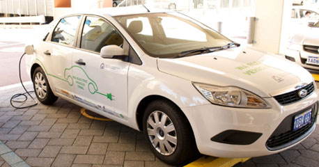
Completed Ford Focus conversion at a charging station
Component Selection
Traction Motor
A high priority for selection of drive components for the electric conversion was to achieve comparable performance as the original vehicle. The Gen 2 Ford Focus uses a 2.0L “Duratec” engine with an official peak power rating of 100kW (140hp) and 184Nm torque. In general an electric motor is sized for continuous duty, but may be operated intermittently well above continuous rating. There are many different electric motor technologies used in electric vehicles. Historically the most common type have been commutated DC, such as Series DC, Seperately Excited (SepEx), or Permanent Magnet (PM) motors. Of these, Series DC are the most common in road-going vehicles.
Recent improvements in power electronics has seen three phase motors and controllers increase in popularity for traction applications. Three phase motors includes AC induction and Brushless DC (also called Permanent Magnet Synchronous Motor or PMSM). However for this project, series DC technology was chosen. The primary reason was one of economics, where available three phase drives were at least twice the price per kW, mostly due to the high cost of the more complicated three-phase controller.
The main downside with series DC is the lack of support for regenerative braking, a technique which uses the motor as a generator to convert the vehicle’s kinetic energy back to electrical charge, and slowing the vehicle down in the process. Regenerative braking can significantly extend driving range for a given battery size.
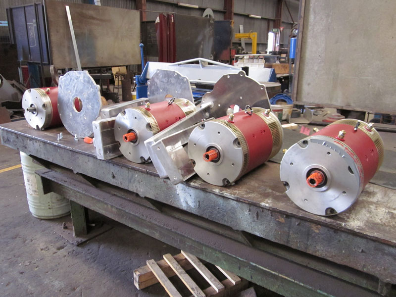
The motor chosen was a NetGain “Impulse 9”, a 4-pole series DC motor of 235mm diameter and 350mm length, with weight approximately 60kg. These motors have a continuous rating of 39kW (205A @ 192V). A larger motor may have been preferred if not for size constraints in the compact engine bay with transaxle gearbox.
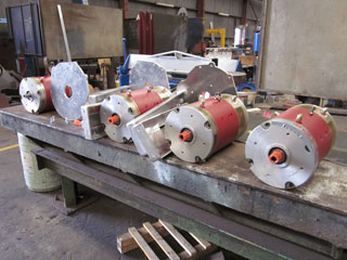
Netgain Impulse 9 motors |
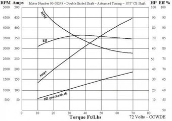
Impulse 9 dynamometer results
(Courtesy Netgain Motors LLC) |
Motor Controller
A total of five different motor controller candidates were evaluated for the Ford Focus, with qualitative results summarised in the following table:
| Options |
Advantages |
Disadvantages |
Curtis 1231C (USA)
144V 500A |
Legacy product with long history. |
Low power for the money. Audible switching frequency at some throttle levels. |
CafeElectric Zilla (USA)
156V 300A |
Good track record for reliability. High power and smooth performance. |
Requires water cooling. Went out of production when trial was about to start. |
ZEVA MC600S (Australia)
144V 600A |
Most economic option. Australian made. |
Less peak and continuous power rating than required. |
Kelly KDHD14100D (China)
144V 1000A |
High power for the cost. |
Jerky starts. Poor reliablility (30% failure rate observed) |
EVnetics Soliton1 (USA)
300V 1000A |
Powerful and smooth operation. Excellent build quality. |
The most expensive option. Relatively short track record. |
Initially the CafeElectric Zilla was chosen, however the product was unfortunately discontinued prior to construction of the vehicles commencing. As a result the EVnetics Soliton1 controller was used instead, despite its 300kW peak power rating being far higher than would be required. (Power output is primarily battery and motor limited in these vehicles.)
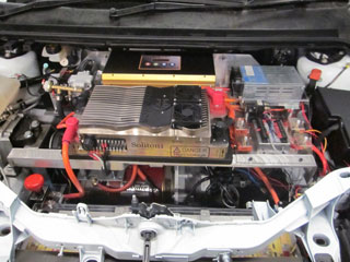
Photo of Focus engine bay, with Soliton1 controller in the centre.
Battery System
Lithium battery technology has been pivotal in the recent resurgence of electric vehicles, being the first battery chemistry to allow useful driving ranges without excessive weight or cost, and is used almost ubiquitously in modern road-going BEVs. There are several sub-chemistries of lithium battery, the most common being Lithium Cobalt (LiCo), Lithium Manganese (LiMn) and Lithium Iron Phosphate (LiFePO4), summarised as follows:
| Chemistry |
Energy Density |
Cycle Life |
Cost* |
| Lithium Cobalt |
120-160 Wh/kg |
500-1000 |
~$0.50 / Wh |
| Lithium Manganese |
90-120 Wh/kg |
500-1000 |
~$0.40 / Wh |
| Lithium Iron Phosphate |
90-120 Wh/kg |
3000-5000 |
~$0.35 / Wh |
* In Australian dollars, as of January 2011.
For this project, LiFePO4 was chosen due to its excellent cycle life which results in the lowest full-life cost by far. LiFePO4 was only invented recently (University of Texas, 1996) so typical service life is as yet uncertain, but is commonly estimated at 10 years. An additional benefit of LiFePO4 is its relative stability; it is not prone to thermal runaway when abused, as is sometimes the case for LiCo chemistry.
Size and configuration of the battery pack was based firstly on the trial requirement for a minimum 100km range. Based on research of similar conversion projects, a worst-case scenario for energy required by such a vehicle was estimated at 200wh/km, suggesting a minimum 20kWh battery pack would be required to safely meet the 100km range requirement.
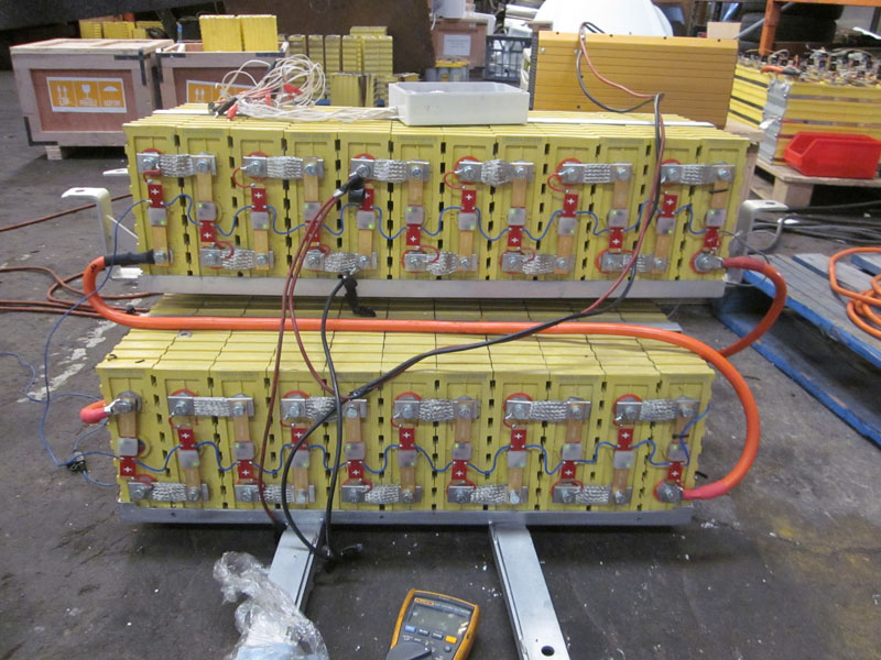
A system voltage of 144V nominal was chosen, primarily due to the prevalence of legacy components such as motors, controllers and chargers designed to work optimally at this voltage. LiFePO4 chemistry has a nominal voltage of 3.2V per cell, so 45 cells were used in series (3.2V x 45 = 144V). With a minimum 20kWh capacity at 144V nominal, a battery capacity of 139Ah or larger was required. The closest match found were ThunderSky TS-LYP160AHA, 160Ah capacity LiFePO4 cells from Chinese manufacturer ThunderSky (now Winston Battery).
Battery Management
Lithium batteries can easily be damaged if their charge voltage exceeds the limits of the chemistry (4.2V for LiFePO4), or if the cell voltage goes below zero as can happen if one cell goes flat before other cells in a series pack while discharging continues. As such it is necessary to use a Battery Management System (BMS) to protect the cells against overcharging or overdischarging, using individual monitoring modules on each cell. Most BMSs also include some form of cell balancing system. BMSs have also been demonstrated to offer substantial improvements to average battery service life (Porebski, W 2004).
For this project, cell modules from Australian company EV Power were chosen. These use a single wire daisy chain with all modules in series, each able to break the signal line if their cell goes out of range. This daisy chain is monitored by a Master Control Unit (MCU) which is able to stop the charger and shut down the drive system if the daisy chain is broken by a module detecting a cell out of range.
Systems Integration
As with any engineering project involving modification of a tightly integrated system, many difficulties were encountered during conversion to electric. Most revolved around the vehicles’ extensive use of CAN bus networking between onboard systems, and the prohibitive complexity of reverse engineering Ford’s CAN bus protocols. As such it was necessary to retain as much of the existing systems and electronics as possible to avoid effecting other devices on the CAN bus which may be depending on intercommunication.
Drivetrain
The simplest option for any EV conversion is to retain as much of the existing drivetrain as possible. This is particularly important in vehicles using transaxles such as the Ford Focus, since the gearbox and differential are integrated. Although many EVs capitalise on the flexibility of an electric motor and only have a single gear, multiple-ratio gearboxes can improve operating efficiency by almost 5% if gears are used to keep motor in optimal efficiency band (Ren, Crolla and Morris, 2009).
Many EV conversions are built clutchless, with the electric motor coupled directly to the gearbox input shaft. Gearshifting is still possible due to the lower inertia of an electric motor armature (compared with the rotating components in an Internal Combusion Engine), which enables the gearbox synchromeshes to do an adequate job of speed-matching. Perhaps more importantly, the wider operating band of an electric motor greatly reduces the need for gearshifting; urban driving can typically be done using a single gear at all times.
Clutchless EVs have the advantage of being legally licensed as automatic vehicles, such that drivers do not require a manual license. However they represent a slightly different driving experience to what most drivers are accustomed to, which can be a hurdle to vehicle acceptance.
One of the EV Trial participants requested conversion of a vehicle with an automatic gearbox.
This is possible with an electric vehicle if the electric motor can be made to idle, such that the automatic transmission fluid can continue to circulate. The EVnetics Soliton1 controller includes a motor idle functionality. However gearshifts in the automatic gearbox in the Ford Focus are controlled by a gearbox computer, and depend on many inputs from accelerator pedal position, vehicle speed, and various engine load sensors. In the absence of the original engine, it was difficult to reproduce correct shifting points.
Vehicle Management System
A custom control system was developed for the vehicles which performs several management functions of the electric drive system:
- Charge/drive interlock: Ensures that the vehicle cannot be driven while the charger is in operation, and vice versa.
Monitoring of BMS cell modules: Able to stop the charger or shut down the drive system if any batteries stray outside safe operating voltage.
- Motor speed limiting: By monitoring motor speed using a hall-effect tach sensor, the system can perform a throttle cut if the motor speed gets too high, to prevent damage.
- Controller precharging: Due to the low-ESR input stage of motor controllers, it is necessary to implement a precharging system to limit current when the controller is first powered up.
- Vehicle status feedback: The device drives an RGB LED and piezo buzzer installed in the vehicle cabin to provide feedback on the vehicle status (e.g idle/driving/charging/battery error).

Photo of the EVMS and 12V control system wiring
Throttle Pedal Integration
Most DC motor controllers require either a 0-5KΩ resistance or a 0-5V voltage level as a throttle signal. For its throttle, the Gen2 Ford Focus uses a Hall Effect Pedal Assembly (HEPA) to send a throttle level to the ECU, and in turn the engine throttle body. HEPA devices are not inherently compatible with either a 0-5kohm or 0-5V throttle, but in the interest of retaining the factory accelerator pedal an interface/translator was developed.
The key component is a digital potentiometer, an integrated circuit which allows a variable output resistance based on a digital input level. For this task a Microchip MCP41010 was chosen, which offers 8-bit (256 step) resolution over the range of 0-10kohm, or in this case 7-bit (127 step) resolution over the required 0-5KΩ. The digtial potentiometer can also be used as a 0-5V throttle by using its output connections as a voltage divider.
The MCP41010 uses Series Peripheral Interface (SPI) bus for the input signal. To ensure isolation was maintained between the traction circuit and the original 12V systems, the SPI bus was optically isolated. Finally a small ATtiny13A microcontroller was used for HEPA level translation and SPI output generation. The following diagram illustrates the basic topology:
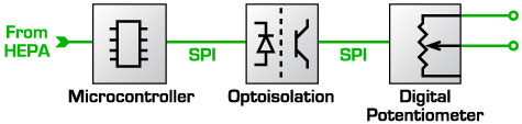
Schema for throttle pedal integration
Power Steering
Most legacy ICE-powered vehicles fitted with power steering systems have used a power steering pump driven via belt drive off the engine crankshaft. In recent years, automakers have been migrating to electric pumps to provide hydraulic pressure for the power steering system, or most recently, direct electric-assist steering columns.
The Gen 2 Ford Focus uses an electric-hydraulic power steering system which was unmodified during the conversion to electric. The pump does, however, rely on a tachometer signal via CAN bus from the Engine Control Unit (ECU) indicating that the engine is running before it will start operating. This was a problem since electric motors are usually stopped when the vehicle is idle, which caused the power steering to also stop whenever the vehicle was stationary.
The solution involved development of a device to simulate and override pulses from the inductive proximity tach sensor for low motor RPM. It was based on a small microcontroller monitoring a separate hall effect tach sensor, installed on the motor’s auxillary shaft, to detect motor speed. If a speed below 600rpm was detected, a relay switched the factory tach sensor for an artificially-generated analogue representing 600rpm. An added bonus of having our own tachometer sensor was the ability to set up speed limiting on the motor at 6000rpm.
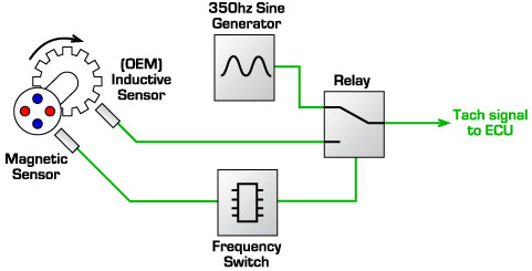
Schema for overriding tachometer below idle
Reusing the fuel gauge
Since these electric conversions were to be used by a wide range of drivers, many uninitiated with electric vehicle technologies, it was important to make them as intuitive to operate as possible. One example of this was to reuse the vehicle’s original fuel gauge in the dash to display battery state-of-charge.
The Gen 2 Ford Focus, as with most vehicles, uses a fuel tank level sensor based on a variable resistance. For this project, a device was used which simulates a variable resistance with a fixed series resistance and Pulse Width Modulated (PWM) switch. PWM duty is determined by state of charge, calcalated from the integral of current flow.
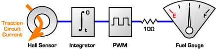
Schema for displaying battery SoC on a factory fuel gauge
Cabin Heating
As well as the importance of cabin heating for occupant comfort, it is a legal requirement in most parts of the world for road-going vehicles to have a source of cabin heating for the purpose of demisting the windscreen (NCOP14, 2011). In ICE vehicles there is a large source of readily-available heat from the engine’s liquid cooling circuit. Most electric vehicles do not produce enough heat from their drive system to allow this option, so an alternative source of heat is required. For this project, three main options were considered:
| Options |
Advantages |
Disadvantages |
| 1) Electric heater element replacing heat exchanger in dash. |
Lowest cost. |
Installation requires disassembly of vehicle dash. Electric elements can emit unpleasant smells when dirty. |
| 2) Create new water circuit with heater and pump. |
Reuses existing heat exchanger in cabin ventillation system. |
Most expensive option due to the need for water heater plus circulation pump. |
| 3) Modify airconditioning to allow for reverse cycle |
Heat pumps are 3-5x more efficient than electric heaters. |
Usually requires significant rework of refridgeration circuit. Not suited to sub-zero climates. |
For this project, option 2 was chosen despite the cost, since it offers the most similar behaviour to the original ICE vehicle, which is highly desirable.
Air Conditioning
Typical ICE-powered vehicles fitted with airconditioning drive the compressor via belt drive off the engine’s crankshaft. For retaining air-conditioner functionality in these conversions, three options were considered:
| Options |
Advantages |
Disadvantages |
| 1) Driving existing compressor via belt drive off auxillary motor shaft. |
Lowest cost due to minimal extra equipment. |
No compressor functionality while vehicle is stopped, since the traction motor also stops. |
| 2) Installing a second, small electric motor to drive the compressor. |
Second motor can run continuously and drive other systems such as power steering pumps (in some vehicles). |
Extra cost and engine bay complexity required for second motor. |
| 3) Replace compressor with independent electric compressor unit. |
Most efficient, compressor can be mounted anywhere for simplest refridgerant circuit. |
Highest cost due to need for new electric compressor and controller, plus re-plumbing. |
For this project, option (1) was chosen in most vehicles for simplicity and economics. The factory airconditioning control systems in the Ford Focus depended on signals from the Engine Control Unit via CAN bus. After conversion, in the absence of the original engine the ECU no longer produced the required signals for the airconditioning system. As such it was necessary to re-engineer a control system. In brief, the control system needed to be triggered by the A/C switch in the vehicle dash, and manage the A/C compressor, engaging and disengaging the clutch as necessary to maintain a correct pressure.
To do this, a signal wire was located in the engine bay corresponding to the status of the A/C switch, which was amplified to drive two relays: one to engage the clutch on the compressor, and the other to switch electric fans fitted to the front condensor. The signal for the clutch relay was also in series with two pressure switches, one high and one low pressure, used to ensure the refridgeration circuit stays within an appropriate operating range.
Brake Assist
Almost all road-going automobiles have vacuum-assisted braking systems, using the low pressure inside the engine manifold as a source of vacuum for the brake master cylinder. In Australia it is a legal requirement for any vehicles manufactured with power-assisted brakes must retain this assistance if converted to electric (NCOP14, 2011). However, unlike ICEs, electric motors offer no inherent source of vacuum, so a separate electric vacuum pump must be installed. The pumps are switched on and off as required using a vacuum switch to maintain a minimum 14inHg vacuum (typically operating with a hysteresis band between 18 – 20inHg).
Remote Telemetry
As with other EV trials, such as the recent Chinese trial described by Ji-Hui, Hui and Ying (2008), an important role of the WA EV Trial is to track vehicle usage patterns and analyse how the vehicles are being used.. To automate data aquisition, telemetry modules were installed in the vehicles. The module chosen was the Astra Telematics AT100. These modules include GPS for location tracking, use 3G mobile network for realtime logging of data back to a server, and have several digital inputs plus one analogue input for vehicle monitoring.
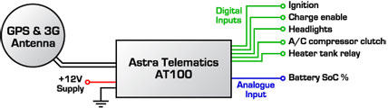
Astra Telematics AT100 telemetry system
Design Overview
Physical Layout
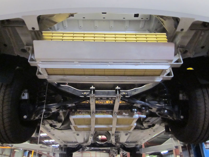
Since the energy density of batteries is far lower than petroleum, most electric vehicles must carry a battery pack much larger than a typical petrol tank. The batteries are by far the largest component added, in both volume and weight. As such one of the biggest challenges with EV conversions is finding convenient locations for battery installation, particularly in cases where cabin space may not be reallocated to batteries.
Each of the 45 LiFePO4 cells used was 209x65x280mm with a mass of 5.6kg, resulting in a total pack volume of approximately 170L and weight of 252kg. With no single location large enough to fit the entire pack, and the need to maintain reasonable weight balance, it was necessary to split the batteries into three separate groups.
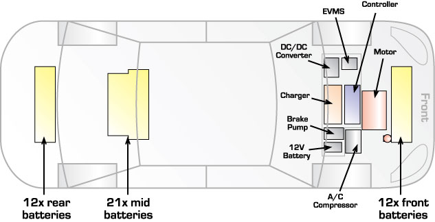
Physical component layout
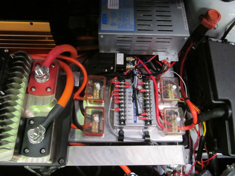
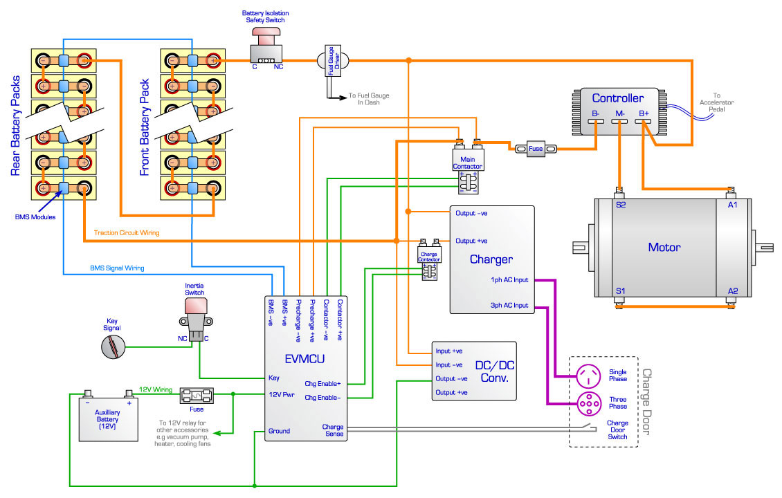
Traction Circuit
The primary three components in any electric vehicle traction circuit are the battery pack, the motor controller, and the motor. Other necessary components include the battery charger, any vehicle management electronics, and a DC/DC converter, a device which charges the 12V battery off the traction battery (basically performing the same function as an alternator in an ICE vehicle). The circuit also includes several safety devices including a main fuse, a battery isolation switch (used during vehicle maintenance, for example), and an inertia switch to automatically disable the traction circuit in the event of a collision.
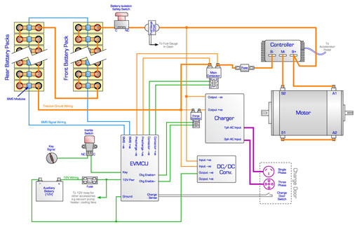
Traction circuit in Ford Focus conversions
Discussion
Difficulties in conversion
Many difficulties were encountered throughout the project. Firstly a high failure rate of commercial products was observed including:
- Catastrophic failures of several motor controllers, presumably due to design flaws.
- Manufacturing faults in several of the battery chargers, as well as embedded software problems, and overheating problems due to heat from the motor warming the engine bay compounded by a lack of airflow at charger’s location.
- High fault rate in BMS modules (approximately 10% with manufacturing faults).
- The high failure rate is likely attributable to the low quantities in which many products for EV conversions are build, and often by small, young companies. Water damage has also been observed in a couple of components with insufficient IP ratings.
Several integration issues were also encountered, including:
- Intermittent rejection of artificial tachometer signal by ECU, resulting in a loss of power steering.
- Intermittent losses of synchronisation between battery state-of-charge and fuel gauge.
Performance
An independent range test undertaken by the University of Western Australia yielded a maximum driving range of 132km, in a typical mixed urban/extra-urban cycle. This represents an efficiency of 175 watt-hours per kilometre, or approximately 10% better than initial estimates. The temperature of the Netgain Impulse 9 motor was measured after several typical driving cycles, with results consistently in the range of 50-60 degrees. This is well within acceptable operating range, since the motors are build with Class H insulation (rated to 180?C) and no permanent magnets to be effected by heat.
Driver Acceptance
At time of this paper, the vehicles been in service for several months. The primary concern has been driver’s concerns about running of out range – sometimes known as “range anxiety”. The occasional problems encountered with correct fuel gauge display compounded this issue greatly, and many vehicles are being retrofitted with aftermarket battery monitoring equipment to address this.
Another common issue has been with the chargers, since the vehicles offer no feedback on whether the charger is running. On some occasions operators had forgotten to turn power on to the charging cable. Future vehicles would benefit from feedback in the charge door indicating a successful commencement of charging.
Most drivers were uncomfortable with clutchless shifting. Vehicles without a clutch were fitted with a gearbox gate to permit only third gear and reverse, preventing any gearshifting. (Third gear provides acceptable performance up to the legal speed limit in Australia.) Most vehicles retained the clutch and full gearbox functionality.
Future of EV Conversions
The very high labour component and lower commodities of scale involved with EV conversions suggests that the future of electric vehicles lies in mass production by automakers. In fact since the commencement of the project, Ford have announced the development of a electric Focus model, scheduled for release in 2012. Of particular interest is the battery pack capacity is almost identical at 23kWh, and they have a similar charger offering both single phase and 3-phase. Ford claim a range of 100 miles (~160km), which is 20% higher than observed with the converted Focuses, but seems plausible due to efficiency improvements possible with a purpose-build vehicle such as an AC induction drive system with regenerative braking.
Conclusion
This project has demonstrated that ICE vehicles can be converted to battery electric drive yielding similar performance, useable range for urban environments, and cost-competitive with early release production EVs. Converting modern vehicles such as the Gen2 Ford Focus can involve challenging integration issues to make the electric drive system compatible with existing systems on the vehicle, and designing conversions to be sufficiently robust and foolproof for the general public can be difficult. However EV conversions can play a valuable role in facilitating early study of driving patterns, infrastructure requirements and public familiarisation of electric vehicles, in preparation for widespread adoption of EVs in the near future.
~Ian Hooper, 18 July 2011
Comments| | Chris on 17th Jun 2012
Fantastic project, honest and detailed report. A real treasure to read in the days of early adopters. Thanks Ian! |
| | Ganeson P.A. on 28th Jun 2012
Absolutely brilliant. Its a must read for starters and also for some of us experienced cows in the business. Ian, Well done. |
| | Stuart on 26th Aug 2012
Fantastic article |
| | Wayne Rumble on 22nd Sep 2012
Great article...thanks for sharing Ian! Look forward to seeing more of these vehicles on our roads and you've proved it's do-able. Thank you |
| | Bob Elton on 30th Oct 2012
Hi Ian,
Great honest article.
What has become of the vehicles now that 12 months or more has passed. Do they continue to be monitored, are the early teething problems you mentioned settled down?? | | |  | | | Ian Hooper on 30th Oct 2012
Hi Bob, yes, the Focuses are all still in service and continue to be monitored/managed under the trial. I guess they must be coming up to the end of the 2-year trial period soon! Since I'm no longer with EV Works I'm a little out of the loop with the latest news, but as far as I know for the most part they've been pretty reliable. I hear they have had occasional problems with component failures (in my opinion, an unfortunate consequence of the EV conversion industry being so small, many components are either from small boutique companies, or "reappropriated" from other industries) so there's clearly a need for better quality EV parts. Perhaps as production EVs become more popular we'll see a trickle down effect of better components for conversions too.
It'll also be interesting to hear the results of the trial at the end, such as how many KMs the cars did over the period, and what the drivers thought of them. (E.g whether range anxiety hindered confidence, in a fleet vehicle environment.) |
|
| | Greg Milligan on 12th Jul 2013
What happens to the vehicles when the trial ends?
Possible batch of relatively affordable EVs to go up for sale? | | | | | | Ian Hooper on 12th Jul 2013
Hi Greg, I believe the trial has ended now for all participants (the final report is available for download from The REV Project's website - quite interesting). Some of the participants chose to keep their EV, and some decided to sell them on. In most cases I think EV Works was commissioned to help find buyers so they'd be the people to contact if you're interested to see if there are any available! |
|
| | Mark Reese on 7th Nov 2013
Hi from mark
A interesting experiment for sure .As with a lot of ev programmes there seems to be a lack of funding .Using cheap batteries and controllers is evident.
The netgain motors seem to be the go but the whole system seems a bit over complicated.
I prefer to use quality products when developing anything and in this case would of used zilla for a controller and charger? ( refer to Manzanita Micro) and Dow Kokam at least for the batt.
BMS seems to be a consistent problem among others. ie airflow BCM I could go on forever.Keep up the good work .
I have a few ideas for road cars.Traction and drive systems.Is anyone interested in developing a axial flux vernier squirrel cage type motor. Forget in wheel motors too heavy and try and tell your insurer you just knocked a corner off the thing yet alone all that weight way out there for no good reason,
In conclusion the whole project seems a bit more of a social experiment over ev development which is not a bad thing at all any interest generated is good and might help with future funding. | | | | | | Ian Hooper on 8th Nov 2013
Hi Mark, thanks for the comments. It would definitely be nice if the Aussie government was a little more interested (and got a little more invested) in electric vehicles. In this case the project was funded by the participants (who paid for the vehicle and conversion) so it had to be done economically. As you say the trial was more a "social experiment" to gauge EV acceptance, rather than trying to push any technical boundaries of electric vehicles. |
|
| | MarkR on 28th Feb 2014
wow guys. I only just found this report and comments. I have soaked up every word. Very informative to a bloke considering a vehicle conversion.
I have about six years experience with solar car racing but have been gathering info towards converting a small commuter for myself.
thanks |
| | MarkR on 12th Mar 2014
wow guys. I only just found this report and comments. I have soaked up every word. Very informative to a bloke considering a vehicle conversion.
I have about six years experience with solar car racing but have been gathering info towards converting a small commuter for myself.
thanks |
| | Anthony on 16th Oct 2014
Very interesting and thanks for the info.Not sure if any EV FOLKS ARE STILL VISITING THIS SITE. I've been researching FOR A MONTH AND JUST FOUND THIS SITE. I;m interested in converting an older van( without power brakes, power steering or computer control mechanisms to start a simpler project).As secondary concept, or possible project, have been thinking about solar panels for the large roof space and also the possibility of very compact fan/wind turbines(small like a desk fan but much stronger)on the roof, or where the radiator would be in an ice/ car. Friends have been using solar to power fridges etc, and the wind is always moving as the car moves.It would be great to see ev vans being made for couriers, tradies (self) and companies like Telstra, Ausgrid etc as well as the little commuter cars. Any comments or suggestions. | | | | | | Ian Hooper on 16th Oct 2014
Hi Anthony, certainly easier (and cheaper) to convert vehicles without power everything and computers! Some people do set up solar charging systems on their EVs, though the charge rate is pretty slow (car-sized panels don't produce a lot of power). Be wary of the wind turbine idea - if it's deployed while driving, you'll lose more power to vehicle drag than what it can generate. I agree about the courier/tradie vans - electric would be a great option for that kind of vehicle, to save on fuel & maintenance costs. |
|
|