
Which BMS products best suit my battery pack?If you're on a budget and just want basic protection, you can use one or more of the 8-cell battery monitors, with up to 8 cells per module for LiFePO4 or 7 cells per module for LiCo / LiNMC / etc. For more a more advanced BMS with automatic pack balancing, higher accuracy, CAN bus, state of charge calculation, temperature monitoring, etc.. To suit low voltage packs we have the 4-12 cell and the 8-16 cell Integrated BMSs. These have almost identical functionality as each other, apart from the different number of cells handled, and also the 8-16 cell unit has an isolated CAN bus which is useful (often required) when connecting the BMS with CAN bus to third party devices like a battery storage inverter. In most cases current sensing is handled by a current shunt connected to the BMS's built-in interface, and you can optionally connect an EVMS Monitor for viewing information from the BMS and doing setup/diagnostics. For packs larger than 16 cells, you can use a number of the 12- or 24-cell BMS (slave) modules, connected to an EVMS3 as the master controller, plus optionally an EVMS Monitor (for viewing info / doing setup) and a CAN current sensor (enabling state of charge calculation, overcurrent protection, etc). This system can accommodate packs with up to 192 cells, including in parallel string arrangements. Current sensing for the EVMS is handled by a device on its CAN bus, either using a hall effect sensor or a shunt interface plus shunt. The shunt option is a little cheaper, but the hall sensor is a little simpler and easier to install. The 4-12 cell and 8-16 cell Integrated BMSs include an internal power supply, to power themselves from the cells they are connected to. This simplifies installation, but means there is some quiescent current consumption (see FAQ entry about it further down). The EVMS requires a 12V power supply to run, which avoids quiescent current consumption from the cells. In most EV applications there will already be a 12V system in the vehicle to use, but if not sometimes you may need a step-down converter to provide power for the EVMS.
Do I need an EVMS Monitor?The EVMS Monitor can be used with the 4-12 cell and 8-16 cell Integrated BMSs as well as the EVMS. Most people find a monitor worth having, for viewing information like state of charge, voltages, temperatures, etc and doing setup / diagnostics, but the EVMS and BMSs are all designed to operate fine if a monitor is not present. If ordering without a monitor, they can be preconfigured before shipping. If so, simply email me after ordering with list of desired settings, or information about the number, size and type of cells in your battery pack.
Can I use ZEVA BMS products with OEM battery modules? (Tesla, LG, Samsung, etc)In most cases yes, but sometimes you will need to make an adapter from the BMS connector on the battery to the connector on the ZEVA BMS module. For Tesla batteries, adapters are available to make this a little easier (e.g Stealth EV's cell tap boards). Many commercial battery modules will be difficult to join in parallel at the cell level because there is no access to the cell terminals, and the BMS balance leads are too small to join cells in parallel (may be exposed to too much current). However they can be joined in parallel at the string level, using separate BMS module(s) on each string. Unfortunately the temperature sensors built-in to battery modules normally won't be compatible with our BMS components. Temperature sensing is normally done using thermistors, which come in all sorts of nominal resistances and rates of change, so it's unlikely that the ones in your batteries match the type that the BMS modules are calibrated for (100Kohm nominal and B25/100 value of 4540K).
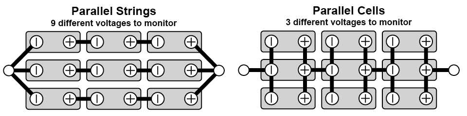
Can I use parallel strings of cells?In general, parallel strings of cells require BMS module(s) on each string, making the BMS more complicated and expensive than a single string of cells. Where possible, it generally makes more sense to join cells in parallel at the cell level, so they can effectively be treated like single larger cells as far as the BMS is concerned. Example picture below to clarify the difference.
However in some cases it is necessary to set up a battery pack as a parallel strings arrangement, and some of our BMS products are able to handle this. The 4-12 cell and 8-16 cell Integrated BMSs are only designed to work with a single string of cells, but the EVMS in combination with the 12- and/or 24-cell BMS modules do support parallel string arrangements. Up to 16 strings in parallel can be used, so long as they are all monitored by 12- or 24-cell BMS module(s) on each string, with no more than 192 cells in total (16x 12-cell modules or 8x 24-cell modules, or some combination thereof). One other consideration with parallel strings of cells is that if there is a problem with one string (such as a cell developing an internal short circuit), it is possible for the other string to dump its energy into the faulty string, which can exacerbate the problem and in the worst case could cause a fire. So for safety it is best practice to have a fuse and contactor for each string, so that they are individually protected and so the EVMS can separate them for safety when the vehicle is not in use, or if it detects a problem. (The string contactors can be powered by the EVMS's Auxiliary Contactor output, so that they are closed whenever the vehicle is either driving or charging. The best arrangement is to have the string contactors on the negative end and the main contactor on the positive end, so that the battery pack is completely isolated from the rest of the traction circuit when not in use, and the strings are separated from each other.)
How is State of Charge calculated?Voltage is not a very accurate way to measure the State of Charge (SoC) with lithium cells, particularly with LiFePO4 types which have a very consistent voltage of around 3.3V over most of their charge range - i.e their voltage doesn't change much over most of the state of charge, and is much more affected by load. Instead SoC is calculated by integration of current over time, i.e adding up all the current that flows in and out of a battery. It is more accurate than using voltage, but is a calculated value rather than an absolute measurement, so it can get out of sync with the battery (particularly when the BMS is first connected to a new battery). When the BMS is first turned on, it may indicate 50% SoC, but this is a default value that won't necessarily match the battery's actual SoC at first, and will need to be synchronised to the battery. The best time to synchronise the SoC calculation with the actual state of charge is at the end of a full charge, when the SoC is known to be 100%. This can either be done using the Reset SoC option button on an EVMS Monitor, or performed automatically by the EVMS once the pack voltage exceeds the "Full Voltage" setting (and after charge current has tapered off). It is best to have the Full Voltage setting about 1V less than the actual maximum charge voltage of the charger, to ensure that the threshold is exceeded reliably.
What voltage should I charge my pack to?Normally the manufacturer's recommended maximum charge voltages for LiFePO4 type cells is 3.65V, and for LiCo / LiNMC / etc it is 4.20V. Often is makes sense to reduce this voltage a little to be kinder on the cells, and increase cycle life. Charging LiCo / LiNMC cells to 4.10V/cell instead will sacrifice about 10% usable capacity but almost double the cycle life, so it is worth doing for long term economics. For LiFePO4, you could consider charging to 3.50V/cell instead; due to the very non-linear charge curve, it won't sacrifice significant capacity (maybe 1%). You also want some margin between the maximum average charge voltage (per cell), and the threshold where a cell is considered over-voltage (and the EVMS / BMS will try to stop the charger), so that some imbalance in the cells is tolerated and the EVMS / BMS won't try to stop the charger before it finishes naturally. If the charger is stopped by the BMS without being able to reach its maximum voltage, you will be missing out on some potential battery capacity (i.e the charger won't perform its Constant Voltage phase, which adds the last 5-20% or so, depending on charge rate). With LiFePO4, the voltage rises quickly as the cell approaches full, which results in small imbalances appearing as significantly diverging cell voltages. To allow for this, you normally want the BMS Max Voltage to be about 0.2V higher than the max charge voltage (per cell). With other lithium chemistries, the voltage curve is more linear, so you may only need a few hundred millivolts, or as little as 0.01V once the BMS has managed to balance the pack well. The pack balancing circuits in our BMS products bleed less than 100mA from high cells (to incrementally pull them down to the lower cells), so generally it's not practical to reduce charge current low enough to fully balance a pack in a single charge cycle. The small balancers may take a long time to correct any large imbalances, but will improve it incrementally over time, and once the pack is balanced they generally won't have to work very hard to maintain it (running for say a few minutes per charge cycle).
Can ZEVA devices share a CAN bus with devices from other manufacturers?Generally it is possible for ZEVA devices to be on the same CAN bus as devices from other manufacturers, but is only beneficial if they have been taught how to communicate with each other to gain some extra functionality, such as with some inverters or chargers. Otherwise, it is safest to have separate CAN buses. With a single CAN bus, all devices need to be running at the same baud rate. It's also important to confirm that there won't be any ID conflicts, and that the bus doesn't get overutilised from too much traffic, which would both cause communication errors. At present, the devices you may wish to have on the same CAN bus as ZEVA devices are battery storage inverters that use SMA or Pylontech CAN protocol, or battery chargers that use TC Charger's CAN protocol. The other possibility would be custom monitors or logging devices that have been programmed to receive and interpret data coming from the ZEVA components.
Can I connect my charger to the EVMS/BMS using CAN bus?The EVMS, BMS12i and BMS16 are all able to control some chargers over CAN bus. Any that use TC Charger's CAN protocol should be compatible, including chargers from TC, Elcon, Ovartech, Dilong, Greatway, and maybe others. Here is a link to the usual CAN protocol, which you can use to confirm compatibility with the vendor before ordering your charger. The normal CAN bus baud rate for ZEVA devices and TC Chargers is 250kbps. It is possible to support different speeds, but all ZEVA devices would need to be reprogrammed to match the charger, which can be a bit troublesome. (CAN bus speed can't be changed in settings, only in firmware.) A CAN bus connection to the charger allows the EVMS to start/stop the charger (enabling BMS protection, so you don't need any charge control relays), and lets the EVMS set the charger's target voltage and output current, which can be configured in the EVMS settings. Also the EVMS Monitor can receive and display information from the charger such as its current output voltage and current, and its status / errors. The EVMS also supports three-phase charging, using three single phase chargers on the same CAN bus, with one charger per phase. It will automatically communicate with all three chargers, and the monitor will automatically display information from all three. The charge current setting applies to each charger, so total charge current will be 3x as much. The three chargers all need to be using different IDs on the CAN bus, as follows: Charger 1 RX: 0x1806E5F4, TX: 0x18FF50E5 Using CAN bus charger(s) also enables the EVSE Interface (in combination with the EVMS) to adjust the charger's output to match the available power from a J1772 charging station.
Which battery storage inverters is the BMS16 compatible with?The 8-16 cell Integrated BMS (aka BMS16) can be used to protect a battery connected to an inverter in several ways. The example wiring diagram in the manual shows how to do it using a contactor between battery and inverter, which the BMS can open if any cells exceed safe voltage range. This can work with most inverters which are able to be configured manually (e.g setting battery capacity and minimum/maximum voltages). Another option is if the inverter has digital inputs for charge enable and discharge enable, these may be connected to the relay outputs on the BMS. In both of these cases, it is best to use somewhat conservative voltage limits with the inverter so that under normal circumstances no cells will exceed safe voltage range, and BMS protection won't trip (unless something has gone wrong). But the best option, where possible, is to connect the BMS to the inverter using CAN bus, so that the BMS can communicate information about the battery to the inverter, as well as tell it to stop charging/discharging if any cells are too high/low respectively. This avoids the need for any contactors/relays for protection, so the LV and HV Relay terminals can be left unused. (Note that you will normally still need a battery isolator switch / circuit breaker between the battery and inverter - a legal requirement in many countries.) The BMS16 supports both SMA and Pylontech CAN protocols, used by those manufacturers, as well as Goodwe (who are owned by SMA), and an increasing number of other companies are adopting one or both of these protocols. It is also used by BYD and LG RESU commercial batteries, so if your inverter includes these in the list of supported batteries, it is likely that it will be compatible - and you can set the inverter to one of these options so it knows what protocol to use, since "ZEVA" won't be in the list. We have no control over the inverter's operation so can't guarantee that the BMS will work with every inverter, and can't provide tech support for setting up the inverter, but if this information suggests that it will probably work you are welcome to purchase a BMS to try, and return for a full refund minus shipping costs within 1 month if you can't get it to work. The BMS will need a current shunt so that it can calculate battery state of charge, which is required information for the inverter. Battery storage inverters normally use a different CAN bus baud rate and format (500kbps and 11-bit IDs) than the default for our products (250kbps and 29-bit IDs), so the BMS needs to be configured to suit the inverter before shipping - please contact us to confirm that you need the BMS to be compatible with an inverter either before or immediately after ordering. Usually a CAN cable will be included with the inverter. It will commonly have an RJ45 connector on both ends, and the two or three wires used for the CAN bus may vary between inverters. So it is normally necessary to remove the RJ45 connector from one end (since the wires connect to the BMS via screw terminals), and figure out which wires are used for the CAN bus. Sometimes it will be listed in the inverter's manual, or you might need to search for the information on the internet. Some inverters will only have CAN L and CAN H wires to connect to the matching terminals on the BMS, some will also have a CAN Ground wire. The CAN bus interface on the BMS16 is isolated / floating, so can safely be connected to any ground level from the inverter. The CAN bus will need at least one 120ohm CAN termination resistor present to function correctly, connected across CAN L and CAN H wires, ideally two (one at each end of the bus). Sometimes the inverter will have one built-in, sometimes it will need one added externally - it should be specified in the inverter's manual. You can have an EVMS Monitor and inverter both connected on the same CAN bus. The monitor has a CAN termination resistor built-in, but the BMS does not. So normally it makes sense to have the BMS in the middle of the CAN daisy chain (i.e Monitor - BMS - inverter). Note about the BMS12i: This device does support CAN bus integration with battery storage inverters, but one caveat is that this BMS does not have an isolated CAN bus - it shares its ground level with the battery pack negative. If the inverter has an isolated CAN bus interface it should be OK, but if it is also non-isolated, it can be problematic to try connecting the two together due to possible ground level mismatch, and it is safest to use the 8-16 cell BMS instead.
Why is my BMS or BMS module getting warm?The BMS modules perform balancing of a pack using power resistors to bleed a small amount of power from any cells above average voltage (or a manually configurable threshold). This generates a small amount of heat (about a third of a watt per cell being balanced) which you may notice through the housing just behind the cell connector. It is normal, and nothing to worry about. The 4-12 Cell Integrated BMS (BMS12i) and 8-16 Cell Integrated BMS (BMS16) also have an internal power supply, located near the power button, which gets a little warm in operation (particularly when the BMS is running i.e not sleeping, and has a monitor attached).
Quiescent current consumption of BMS12i and BMS16A general warning about any BMS that powers itself from the cells it is connected to, is that the BMS itself will very slowly discharge the battery pack. Both our BMS12i and BMS16 products will turn themselves off if any cells get extremely low to avoid further discharge, but it is best to design your system so that this won't happen often if ever (since very deep discharges tend to shorten a cell's cycle life). Putting the BMS to sleep (connecting its Sleep terminal to Ground) will significantly reduce quiescent current consumption, and is recommended whenever the system is not in use. Or if it won't be used for a long time (say weeks or longer), it is best to turn off the BMS completely, usually via the Power Off option button on the monitor, or unplugging the cell connector.
Why am I getting a precharge error?(Applies to both the Smart Precharger, and the EVMS's internal precharger.) The precharger may show an error either immediately, or if precharge hasn't succeeded after 5 seconds. If it is failing immediately, it normally means the precharger couldn't detect any voltage across the main contactor on startup. This can happen if the controller is already precharged, or if there is a break somewhere in the traction circuit (e.g an auxiliary contactor somewhere that hasn't closed) when precharge is starting. It can also happen if there is an open-circuit "downstream" of the contactor - for example if no motor controller is present. If the controller is already precharged, it may take some time for the capacitors in the motor controller to lose enough charge for the precharger to detect a valid load before precharging. Some controllers self-discharge faster than others. If yours is taking a long time, it is possible to add a bleed resistors across its input power terminals to speed up capacitor discharge. You can use say a 10Kohm 5W resistor for 150V systems, or 40Kohm 5W for 350V systems. It is fine to leave this permanently in-circuit as it is not a significant load (e.g negligible effect on range). If it is trying to precharge for 5 seconds then timing out, the usual explanation is that something downstream of the main contactor is consuming power while precharge is trying to happen. DC/DC converters are the common culprits which will try to start running as soon as they get some voltage, which sucks up all the precharge current. The best option is to switch them on using a separate contactor / relay, not the main contactor. If this isn't possible, or if say it's the motor controller itself that is consuming power while precharge is still happening, you might need a beefier precharger that can carry more current to overcome the quiescent current consumption. Unfortunately our prechargers have limited output current due to the solid state relay used. It's also possible for precharge to timeout even with a purely capacitive load if it's too big, but extremely rare for EV motor controllers to have this much input capacitance. (Would usually be found on megawatt+ sized controllers.)
How can I apply firmware updates to ZEVA devices myself?It is possible to change the firmware in most ZEVA devices, but some extra equipment and setup is required, and it will probably involve a learning curve if you haven't programmed microcontrollers before. You will need an AVRISP type programmer (a USBASP is the most common and economical option), and software such as AVR Studio (IDE) or AVRDude (command line tool) to transfer the code to the board. The programming port on ZEVA devices is a 5x1 row of holes on the PCB, normally located near the main microcontroller. It is not the usual 5x2 or 3x2 pin header found on most AVRISP type programmers, so you will need to create an adapter from one to the other using 5x wires and some common 0.1" pitch pin headers. The pin order for the ZEVA port is GND, MOSI, MISO, SCK, RESET, with the GND end labelled on the board. (The pinout for the AVRISP headers can be found via Google.) You can use a 5x1 row of common 0.1" header pins and hold them against the holes in the board while programming - usually no need to solder anything to the PCB. The device will need to be powered during programming. In the case of the BMS12i and BMS16, you will need to hold the power button down during programming to maintain power to the microcontroller. The 5V wire on the AVRISP programming connectors is used by the programmer to detect if the target has power, not to provide power to the target. The programming port on ZEVA devices does not have this 5V pin. Some programmers won't care, some do, but in most cases can be overridden (e.g AVRDude will just ask for confirmation before proceeding). At worst, you may need to locate a 5V point on the PCB and attach an extra wire to this during programming. Make sure you have the correct type of microcontroller selected when programming. The EVMS Monitors are normally AT90CAN64 (sometimes AT90CAN128), the 8-cell Battery Monitors are normally ATmega48PA, and all other devices are normally ATmega16m1 (or sometimes ATmega64m1). Some simpler devices such as the Smart Prechargers, Fuel Gauge Drivers and Low Voltage Cutoffs do not have a programming port on the PCB and need the microcontroller to be removed for programming. |
|||||||
Zero Emission Vehicles Australia © 2025 :: Terms and Conditions, Privacy Policy, Payments and Delivery, Warranty and Returns